
Radial-free collinear omni-directional triband half wavelength antenna with virtual ground, single coaxial cable feedpoint, and with minimal interaction of adjustment between bands

a triband half wavelength, collinear technology, applied in the direction of antennas, antenna details, antenna feed intermediates, etc., can solve the problems of increasing manufacturing costs, reducing returns effectively, lessening robustness and portability, etc., to achieve good omni-directional rf radiation performance, good swr performance, and more gain

Active Publication Date: 2017-03-28
FONG EDISON
View PDF11 Cites 6 Cited by
  • Summary
  • Abstract
  • Description
  • Claims
  • Application Information

AI Technical Summary

Benefits of technology

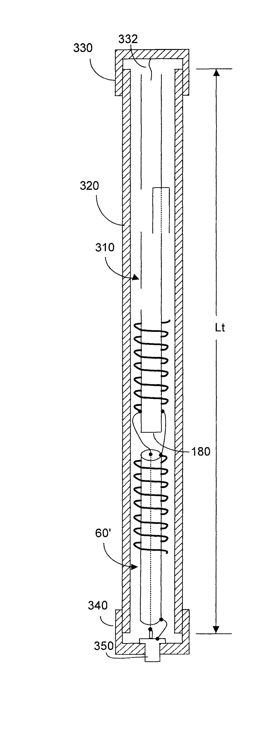
The present invention provides a triband antenna that can be used over three different frequency bands with good performance, including a half-wavelength end-fed vertical dipole for VHF and UHF bands and a half-wavelength center-fed vertical dipole for the intermediate band. The antenna exhibits good omni-directional RF radiation performance and operates without radials or an absolute ground. It may be easily fabricated from inexpensive twinlead and mounted within PVC tubing for protection against weather and UV radiation. The RF radiation at the intermediate band does not interfere with the RF radiation in the other bands, and the overall antenna performance is not affected when adjusting the lengths of the various bands. The cost of the materials is minimal, and the assembled antenna can be easily mailed in a lightweight package. The detuning effects of the PVC pipe on the antenna performance are taken into account when fabricating the antenna.

Problems solved by technology

Ground radials undesirably increase antenna wind load thus lessening robustness and portability, and increase manufacturing cost.
However a point of diminishing returns effectively occurs at about four elements in that marginal further increase in gain does not warrant the cost of the additional elements.
If the radials are on the ground, they may be damaged from being walked upon.
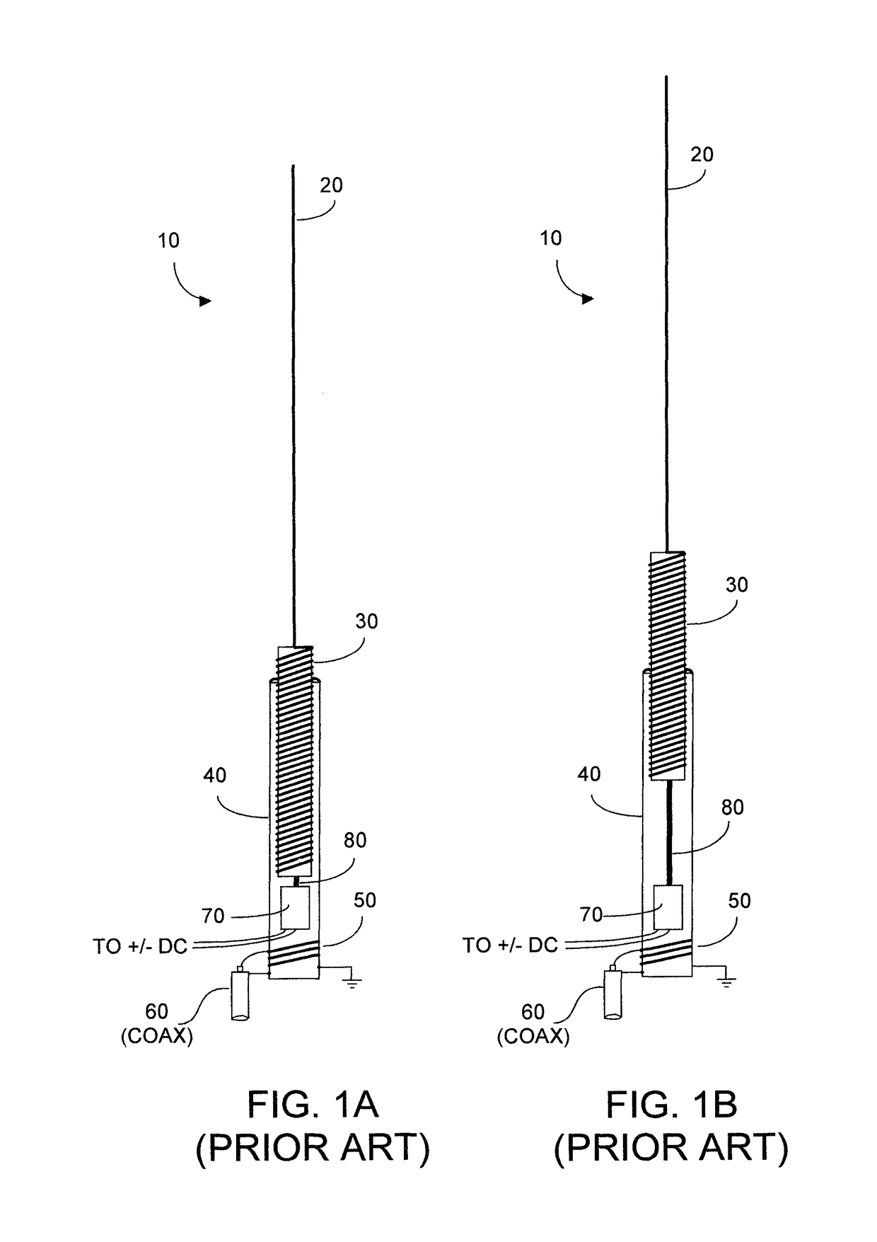
Further, the electrical conductivity between the radials and the shield of coaxial cable 60 will inevitably deteriorate over time.
However the sleeve configuration can make it difficult to achieve desired low SWR due to inherent coupling between the outer shield conductor of coaxial cable 60 and the wall of sleeve 150.
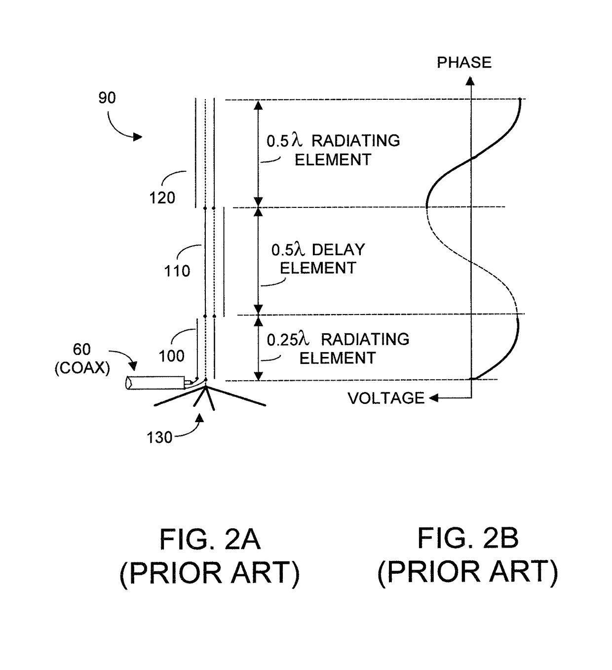
Ideally the phase delay and radiation patterns associated with element 200 would be perfectly out-of-phase, but in practice some phase error and associated antenna inefficiency will exist.
However such solutions are not optimum because losses and tolerance changes in the L and C components vary over time, which can reduce effectiveness of the desired delay function.
With radials bent downward from say 0° (i.e., horizontal) to about 45°, and disadvantageously a relatively high angle of radiation will result.
This distortion results because the third harmonic of VHF is UHF, and has the undesired characteristic that perhaps 75% of the radiation emanates up into the sky.
Robustness is compromised by the inherent weakness of solder joints, especially in inclement weather.
The overall antenna is about 1.6 m from top-to-bottom, is rigid but fragile, and is not readily shippable.
However on balance, the cost, weight, lack of robustness, and difficulty in transporting a copper J-pole mitigate against using such material.

Method used


Image

  • Radial-free collinear omni-directional triband half wavelength antenna with virtual ground, single coaxial cable feedpoint, and with minimal interaction of adjustment between bands
  • Radial-free collinear omni-directional triband half wavelength antenna with virtual ground, single coaxial cable feedpoint, and with minimal interaction of adjustment between bands
  • Radial-free collinear omni-directional triband half wavelength antenna with virtual ground, single coaxial cable feedpoint, and with minimal interaction of adjustment between bands

Examples


Embodiment Construction

[0052]FIG. 8 depicts applicant's initial attempt to design a triband antenna. Antenna 280 comprises a DBJ-1 (WB6IQN) dual-band VHF-UHF stacked J-pole twinlead antenna portion 260 (similar to antenna 260 in FIG. 6A), comprising sections 262, 264, 266, and 268. However at the bottom of the passive non-radiating impedance transform section 262 of VHF-UHF J-pole 260 there is coupled a 220 MHz 0.5″ diam. copper J-pole antenna portion 288 with copper quarter-wavelength stub 284 (similar to the 220 MHz portion 284 of antenna 280 in prior art FIG. 7). Two lengths of coaxial cable, e.g., RG174A or the like, are disposed within copper antenna portion 288. The center conductor of one coaxial cable is coupled to lead 2 of the above-lying stacked J-pole assembly, and the center conductor of the other coaxial cable exits via an entry hole from member 288 and is soldered to the shell of copper stub member 286. The ground shield of this second coaxial cable is soldered the copper housing 288 near t...


PUM


Abstract

An omni-directional triband antenna operates without ground radials with gain commensurate with a half wavelength vertical on each band. The triband antenna includes a dual-band twinlead J-pole providing half wavelength radiators for UHF and VHF, and an impedance transformer defining feedpoints to which a length Lc of coaxial cable is attached. The Lc lower end is the triband antenna connector port. Intermediate band radiators are first and second wire elements that collectively are a half-wavelength at the intermediate band. The first element is wound helically about the impedance transformer, with upper end floating and lower end connected to a first feedpoint. The second element is wound helically about the Lc upper portion of coaxial cable, with upper end connected to the remaining feedpoint, and lower end of the element floating. The helical windings radiate vertically and there is no cross-interference between antenna radiation in any of the three bands.

Description

FIELD OF THE INVENTION[0001]The invention relates generally to antennas that radiate and receive radio frequencies (RF) preferably for use in the very high frequency (VHF) range (about 140 MHz-170 MHz), an intermediate range (about 220 MHz-225 MHz), and ultra-high frequency (UHF) range (about 420 MHz-470 MHz), which antennas do not require radials or connection to absolute ground. Preferably such antennas should be mechanically robust over extremes of temperature and wind, and should be relatively inexpensive to mass produce and transport, with a length under about 2 m. Further, such antennas should exhibit gain commensurate with a half wavelength dipole over at least three bands ranging from VHF to UHF, including operation intermediate VHF and UHF frequencies. The antenna should exhibit minimal inter-band interaction if antenna adjustments are made, should have a single coaxial cable feed point, and should be relatively maintenance free.BACKGROUND OF THE INVENTION[0002]Radio freque...

Claims


Application Information

Patent Timeline
IPC IPC(8): H01Q9/04H01Q9/18H01Q1/36H01Q21/30
CPCH01Q21/30H01Q9/18H01Q1/362H01Q1/3283
Inventor FONG, EDISON
Owner FONG EDISON
Learn More