Turbulence-inducing devices for tubular heat exchangers

a technology of turbulence-inducing devices and heat exchangers, which is applied in the direction of heat exchange apparatus, fluid heaters, lighting and heating apparatus, etc., can solve the problems of increasing heat transfer resistance, lowering the heat transfer coefficient, and heating or cooling fluids in the tubes to foul, so as to enhance the heat transfer coefficient and enhance the efficiency

Active Publication Date: 2017-03-28
SAUDI ARABIAN OIL CO
View PDF92 Cites 3 Cited by
  • Summary
  • Abstract
  • Description
  • Claims
  • Application Information

AI Technical Summary

Benefits of technology

[0017]The above objects and further advantages are provided by the apparatus of the present invention for promoting turbulence in the tubes of a heat exchanger conveying the heat transfer fluid that in one embodiment comprehends a turbulence-inducing element formed with a conical upstream portion, from the base of which a second portion extends downstream. In one embodiment, the second portion is convex or hemi-spheroid in shape. In another embodiment, the second portion is conical in shape. In yet another embodiment, the second portion is shaped as a conical frustum. In yet another embodiment, the second portion is shaped as a truncated convex shape with a rounded edge surface. In another aspect of the present invention, longitudinal grooves and / or protrusions are formed on the exterior surfaces of the turbulence-inducing elements. The solid or closed downstream ends of the elements prevent accumulation of deposits.
[0021]Preventing formation of a quiescent boundary layer enhances the heat transfer coefficient and breaks down or prevents formation of the stagnant film on the inner surface of the tubes associated with the boundary layer. The apparatus and method of the invention also result in a thorough mixing of the heat transfer fluid as it passes through the tube, thereby enhancing its efficiency.

Problems solved by technology

Another factor that must be considered in designing heat exchangers is the tendency of heating or cooling fluids to foul in the tubes through which they pass.
One detrimental effect of fouling is a lowering of the heat transfer coefficient.
The thermal conductivity of the fouling layer is less than that of the tube material, which increases the heat transfer resistance, reduces the efficacy of the heat exchanger, and increases the tube skin temperature.
Another negative effect of fouling is that the formation of depositions on the interior surface of the tubes reduces their cross-sectional area, causing increased resistance to the fluid flow and an increase in the pressure drop across the unit.
In refinery and petrochemical plants, problems caused by tube fouling are very expensive to remedy.
Capital expenditures are higher due to the increased size of the heat exchanger (e.g., selecting heat exchangers with 10-50% greater surface area to accommodate conventional fouling expectations), the associated increase in requisite area within the plant, the higher strength and size foundations, and the extra transport and installation costs.
Furthermore, the cost of operating the unit is increased due to additional fuel, electricity or process steam requirements.
In addition, production losses occur during planned and emergency plant shutdowns due to fouling and associated system failures.
In addition to the aforementioned costs associated with selecting a larger heat exchanger, an additional concern is that the excess surface area calculated with a fouling factor can result in start-up complications and actually encourage more fouling.
The effect of increasing the number of tubes is to decrease the fluid flow velocity, thereby increasing the likelihood of fouling.
Similarly, increasing the tube length results in lower fluid pressure, also increasing the likelihood of fouling.
These devices, which generally require direct physical contact with the inner tube surface, have not been especially successful in preventing fouling.
Furthermore, in the context of a heat exchanger's transferring tube, fouling will predictably occur at the interface of the Pielock device and the tube's inner surface.
Therefore, application of this structure is necessarily limited to vertical shell-and-tube heat exchangers.
The above-described references each have drawbacks that render them unsuitable for minimizing or preventing fouling.
However, fouling will eventually accumulate at, and proximate to the attachment points, which hinders removal of the inserts and thus complicates cleaning the inner surface of the tube.

Method used


Image

  • Turbulence-inducing devices for tubular heat exchangers
  • Turbulence-inducing devices for tubular heat exchangers
  • Turbulence-inducing devices for tubular heat exchangers

Examples


Embodiment Construction

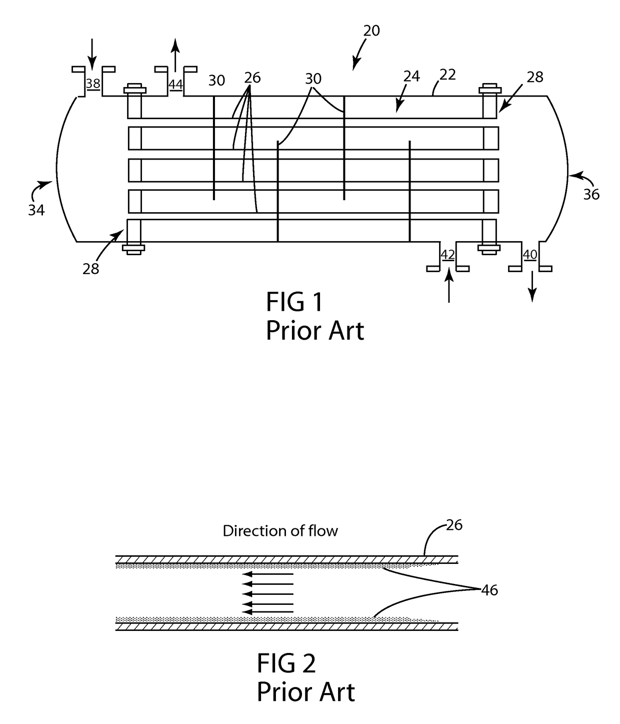
[0046]Referring to FIG. 1, there is shown a longitudinal cross-sectional view schematically depicting the arrangement of elements in a typical shell-and-tube heat exchanger 20 of the prior art. A bundled tube heat exchanger is a well known configuration of a type of heat transfer equipment in which a plurality of tubes convey a heat transfer fluid. By means of the thermal conductivity of the tubes, heat is transferred to a receiving fluid that contacts the exterior surface of the tubes.

[0047]Exchanger 20 includes a shell 22 and a tube set 24 having a plurality of tubes 26. The tubes 26 are supported at their ends by tube sheets 28, also known as end plates. In the typical construction of a bundled tube heat exchanger, a series of baffles 30 are provided through which the plurality of parallel tubes 26 pass.

[0048]In operation, heat transfer fluid is introduced via a tube set inlet 38 proximate to the first end 34 of the shell-and-tube heat exchanger 20, passes through the tubes 26, a...


PUM


Abstract

A heat exchanger tube for conveying a heat transfer fluid, into which one or more turbulence-inducing elements are fixedly positioned on a supporting member extending in spaced relation along the central axis of the tube. The turbulence-inducing elements have a first portion facing upstream and a second portion facing downstream. The entire exterior surface of the first portion forms a continuous solid surface that blocks and deflects the path of the flowing fluid.

Description

RELATED APPLICATIONS[0001]Not ApplicableBACKGROUND OF THE INVENTION[0002]Field of the Invention[0003]This invention relates to tubular heat exchangers, and in particular to turbulence-inducing devices positioned in the tubes of the tubular heat exchanger that minimize or prevent fouling caused by the heat transfer fluids and enhance or maintain the overall heat transfer coefficient over the operational life of the tubular members.[0004]Description of Related Art[0005]Heat exchangers are found in many industrial and commercial applications. In the design of heat transfer equipment, an important factor includes the footprint of the exchanger relative to the capacity of fluid that is to be heated or cooled (the “receiving fluid”), as well as the requisite flow of the heating or cooling fluid (the “transferring fluid”). The heat transfer coefficient between the transferring fluid and the receiving fluid should be maximized to achieve the smallest allowable footprint of the heat exchange...

Claims


Application Information

Patent Timeline
Patent Type & Authority Patents(United States)
IPC IPC(8): F28F13/12F28F13/06
CPCF28F13/06F28F13/12
Inventor AL-OTAIBI, ABDULLAH M.
Owner SAUDI ARABIAN OIL CO
Why Eureka
Try Eureka