
Optical fibre installation apparatus

a technology of optical fibre and installation apparatus, which is applied in the direction of cables, cables laying apparatus, instruments, etc., can solve the problems of physical damage, affecting the performance of optical fibre, and prone to buckling of optical fibre units

Active Publication Date: 2017-01-03
BRITISH TELECOMM PLC
View PDF14 Cites 1 Cited by
  • Summary
  • Abstract
  • Description
  • Claims
  • Application Information

AI Technical Summary

Benefits of technology

The patent describes a system that uses a low inertia motor and a current limiting device to prevent the cable from advancing too quickly when it meets resistance. This results in a more responsive system that can automatically slow down the rate of advance without increasing the force applied to the cable. This helps resolve snagging conditions and allows the installation to resume normally.

Problems solved by technology

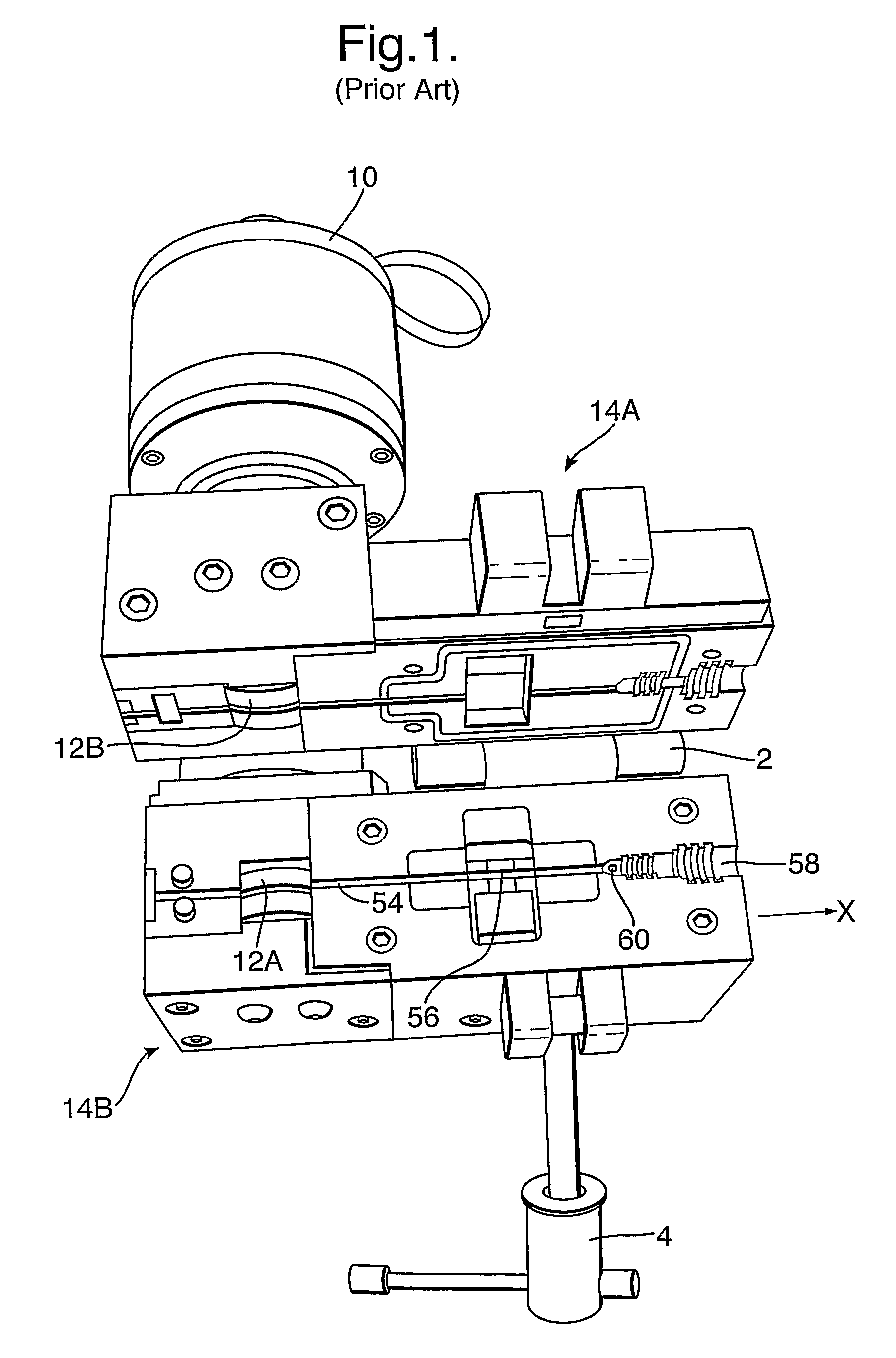
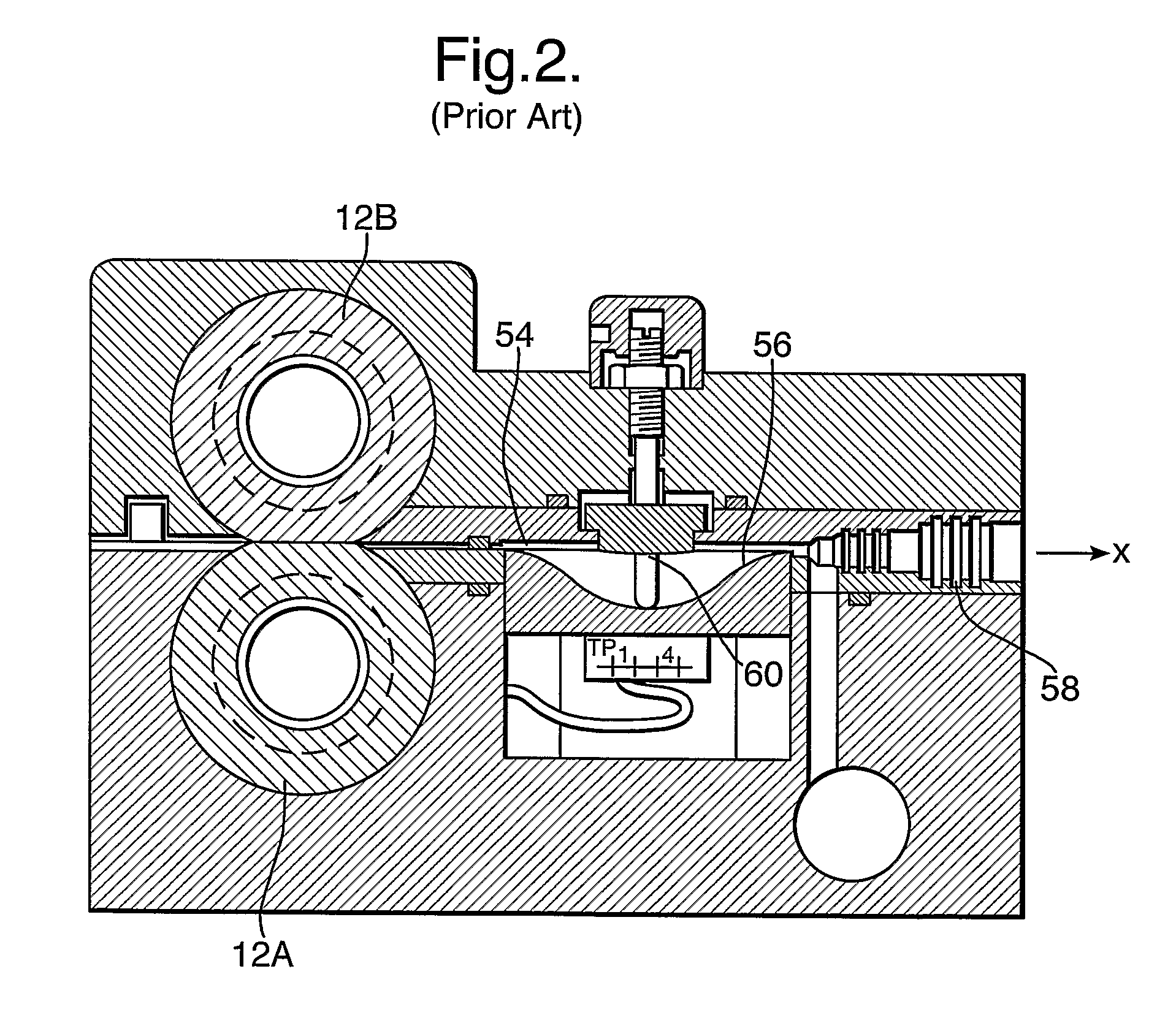
First, it was found that the fibre unit was susceptible to buckling during installation. As discussed in EP253636, optical fibre is flexible and necessarily smaller in cross section than the fibre tube it is populating. For example, part of the advancing fibre unit could stop moving within the tube due to excessive friction build up between the fibre and the interior of the tube. A buckle develops if the blowing head continues to drive the fibre unit regardless. A buckled fibre unit could adversely affect the performance of the fibre when installed, or even physically damage it. At the least, buckling would delay the installation process.
However this method is unlikely to achieve that end as the method and apparatus proposed is not sufficiently responsive nor repeatable owing to a hysteresis loop lag in a magnetic clutch system.
A second problem concerned the amount of air leakage from the blowing head.
Deformable seals were typically used to defend against air leakage, but these proved to lack durability on account of its exposure to the glass microspheres which coat the protective sheath of a fibre unit or bundle.
As deformable seals are typically made from rubber or such materials, they are highly susceptible to damage by the glass, making frequent replacement a costly necessity.
As a result of air leakage from the blowing head, the amount available to generate the required viscous drag within the fibre tube decreases.
It is thus necessary to employ expensive high-volume air compressors to compensate for the loss of air.
In addition to the expense of procuring and operating such compressors to make good the wastage, the weight and bulk of the machinery has necessitated the employment of more than one operative, with associated cost implications.
A third problem arises from developments in the size of fibre bundles (comprising a number of fibre units or members) and the size of fibre tubes.
Yet another problem with blowing heads of the prior art has been cost: cost in terms of manufacture and in operation.
For residential users however, “last mile” issues—where ultimate users still use limited bandwidth copper wire in an otherwise all-fibre network—arise in no small part to the cost-sensitivity of such customers.
Indeed, cost is a major factor in determining the rate of adoption of FTTH.
As cost used to be less of a consideration, the blowing heads of the prior art tended to be seen as specialised pieces of equipment tooled from expensive materials.
Owing to high levels of air leakage in use, powerful and expensive air compressors had to be used with the prior art blowing heads.
In short, prior art blowing heads are too expensive to make and to use, to be sensibly feasible for mass deployment to provide fibre connections to private premises.

Method used


Image

  • Optical fibre installation apparatus
  • Optical fibre installation apparatus
  • Optical fibre installation apparatus

Examples


Embodiment Construction

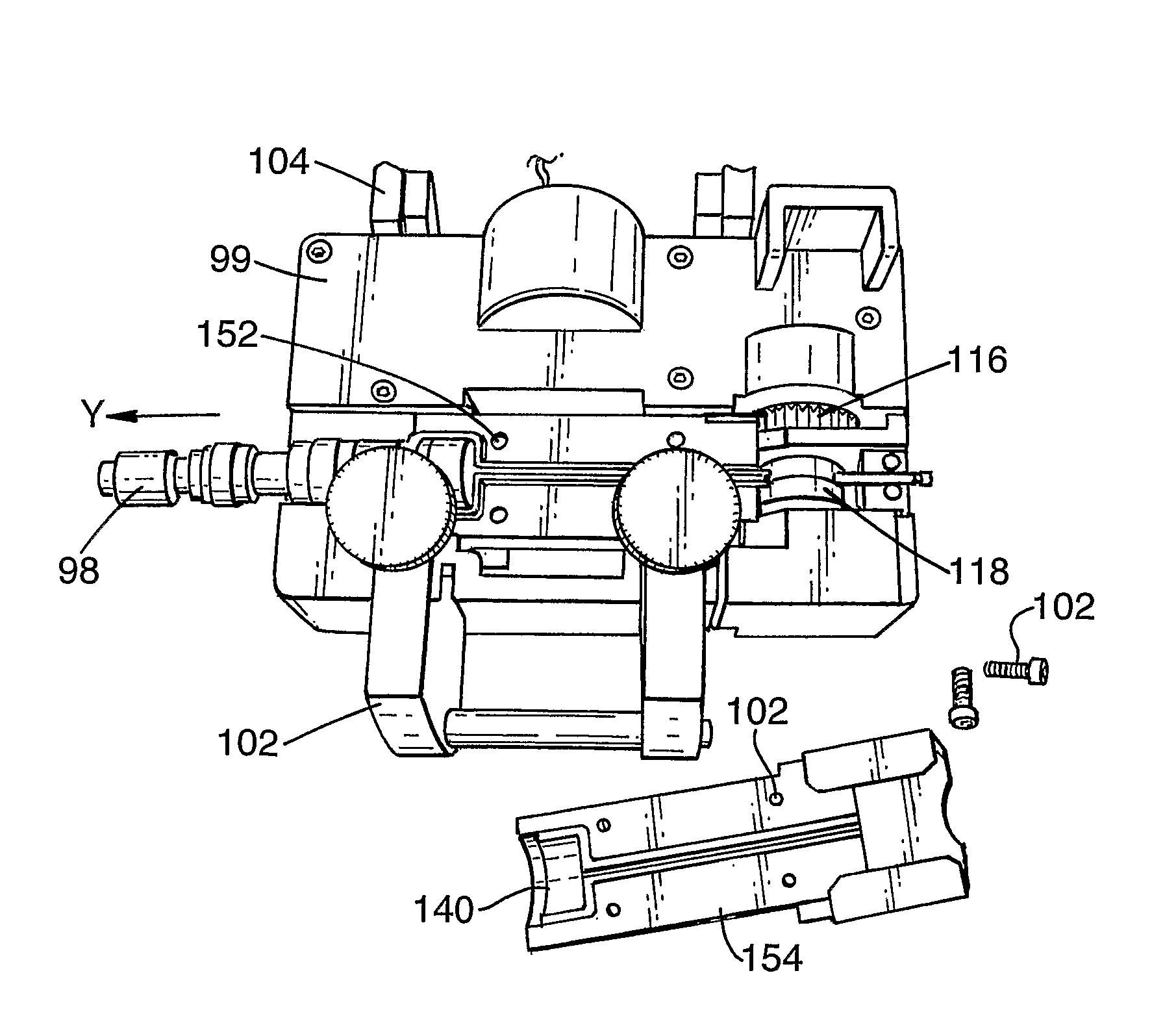
[0021]The applicants have now devised a new blowing head which addresses the above problems, to provide a solution to overcome the issues related to fibre buckle, excessive air loss, bi-directional installation, inflexibility in use with different-sized fibre bundles and tubes, and cost.

[0022]According to a first aspect of the invention there is provided a blowing head for installing blown cable, comprising a low-inertia motor using electrical current, operable to obtain the advance of the cable within the blowing head, adjusting means operable to vary the level of current of the motor, and low-inertia sensing means to sense movement and changes in the level of movement of the cable within the blowing head, wherein in use the adjusting means varies the level of current used by the motor in response to changes in the level of movement sensed by the sensing means, and wherein the varying level of current does not exceed a maximum current level.

[0023]According to a second aspect of the...


PUM


Abstract

A blowing head for installing blown cable, comprising a low-inertia motor using electrical current, operable to obtain the advance of the cable within the blowing head, adjusting means operable to vary the level of current of the motor, and low-inertia sensing means to sense movement and changes in the level of movement of the cable within the blowing head, wherein in use the adjusting means varies the level of current used by the motor in response to changes in the level of movement sensed by the sensing means, and wherein the varying level of current does not exceed a maximum current level.

Description

[0001]This application is the US national phase of international application PCT / GB2006 / 001134 filed 29 Mar. 2006 which designated the U.S. and claims benefit of GB 0506589.1, dated 31 Mar. 2005, the entire content of which is hereby incorporated by reference.BACKGROUND[0002]1. Technical Field[0003]This invention relates to methods and apparatus for the installation of telecommunications cables, in particular optical fibre installed into pre-installed optical fibre tubes by “blowing” techniques.[0004]2. Description of Related Art[0005]The method and apparatus used to install optical fibre transmission lines into optical fibre tubes or ducts using the viscous drag provided a high-speed flow of a fluid medium, often air, is known from EP108590 and subsequent publications. A blowing head is used for the installation of the optical fibre unit into the optical fibre tubes or ducts. (In this description, references to “fibre” and “fibre units” shall be deemed to include individual fibre ...

Claims


Application Information

Patent Timeline
Patent Type & Authority Patents(United States)
IPC IPC(8): B65H59/00G02B6/44H02G1/08
CPCG02B6/4464H02G1/08H02G1/086G02B6/52
Inventor BARKER, PHILIP AANDREWS, PAUL MLAIDLER, GRAHAM ANOLDE, KEITH E.
Owner BRITISH TELECOMM PLC
Learn More