
Machine for binding reinforcement bars

a technology of reinforcement bars and machines, applied in the field of machines for binding binders, can solve the problems of looser connection and lower tension of twisted wires, and achieve the effect of increasing the tension of wires

Inactive Publication Date: 2012-05-31
TYMATIC
View PDF4 Cites 4 Cited by
  • Summary
  • Abstract
  • Description
  • Claims
  • Application Information

AI Technical Summary

Benefits of technology

[0006]The present application aims to reduce this problem and provides a machine for tying a wire around a pair of bars comprising means for passing said wire in a loop around the bars and a twisting head for twisting the ends of said loop together, said twisting head comprising at least one pivoting clamping member for clamping the end of the wire against a clamping surface, said clamping member having a curved surface which applies a clamping force to the wire which increases as the tension in the wire increases.
[0007]Thus the machine of the invention increases the amount of grip applied to the ends of the wire as tension increases in the wire during twisting. This helps to overcome the problems encountered in use of prior art devices in which the amount of grip could be influenced by uncontrolled external factors. The clamping surface is preferably part of the twisting head or is fixed relative to the twisting head.
[0010]Where the clamping member or members applies a clamping force that prevents slipping, preferably the twisting head is resiliently mounted so as to be drawn towards the bars against a resilient bias force during twisting. This has the effect of limiting the tension in the wire so that it is less prone to breaking under excess tension. Preferably said resilient mounting is provided by a sprung housing, stand or frame which engages the object(s) being tied. Alternatively, the compressible portion of the machine may be provided elsewhere, e.g. between a frame or housing and the parts of the machine mounting the twisting head.

Problems solved by technology

However, if the surface of the wire or the interior gripping surface inside the machine should be contaminated with oil or grease, or indeed even if the machine is used in damp conditions, the degree of friction actually exhibited may be less than intended leading to a lower tension in the twisted wire and therefore a more loosely tied connection.

Method used


Image

  • Machine for binding reinforcement bars
  • Machine for binding reinforcement bars
  • Machine for binding reinforcement bars

Examples


Embodiment Construction

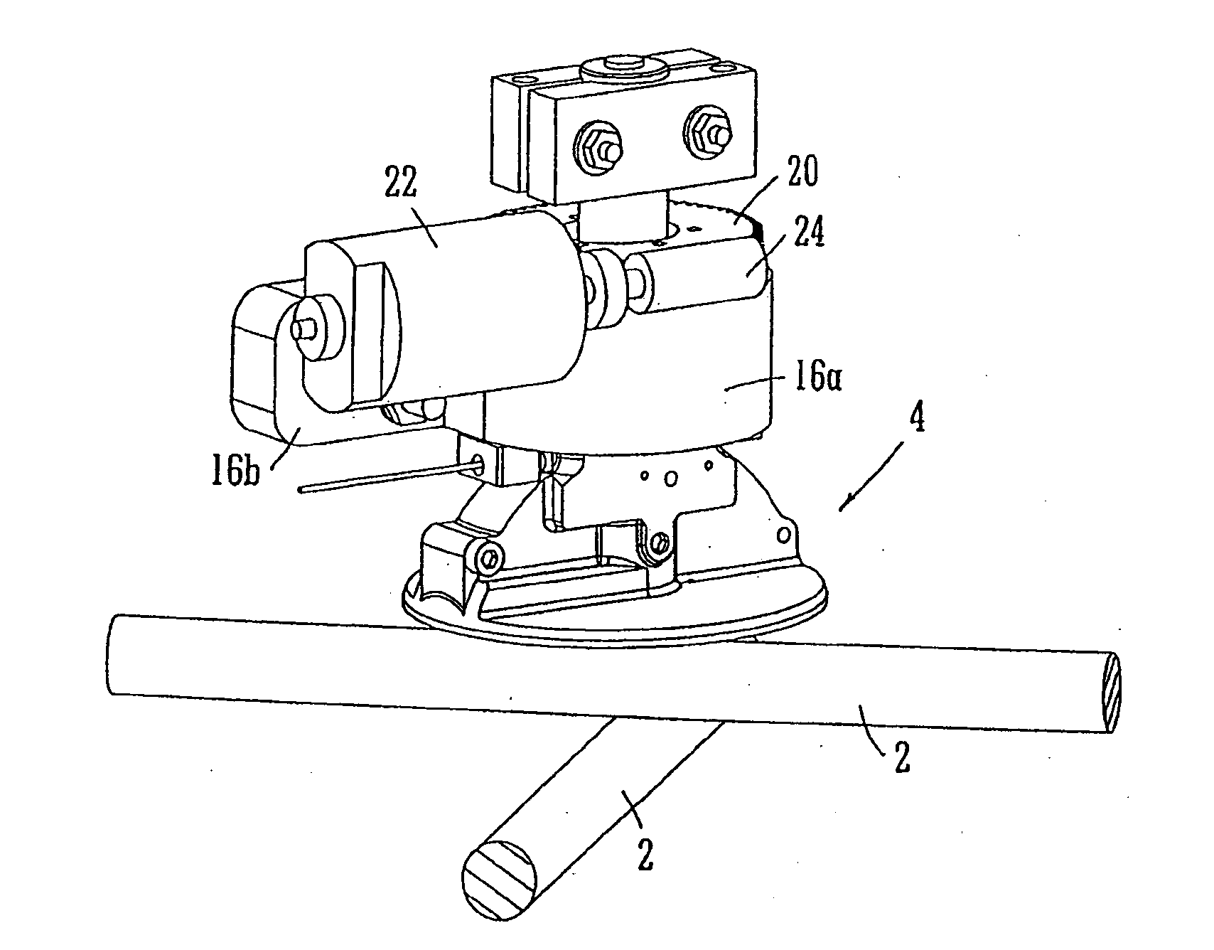
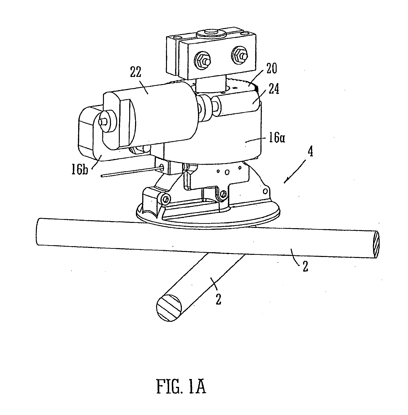
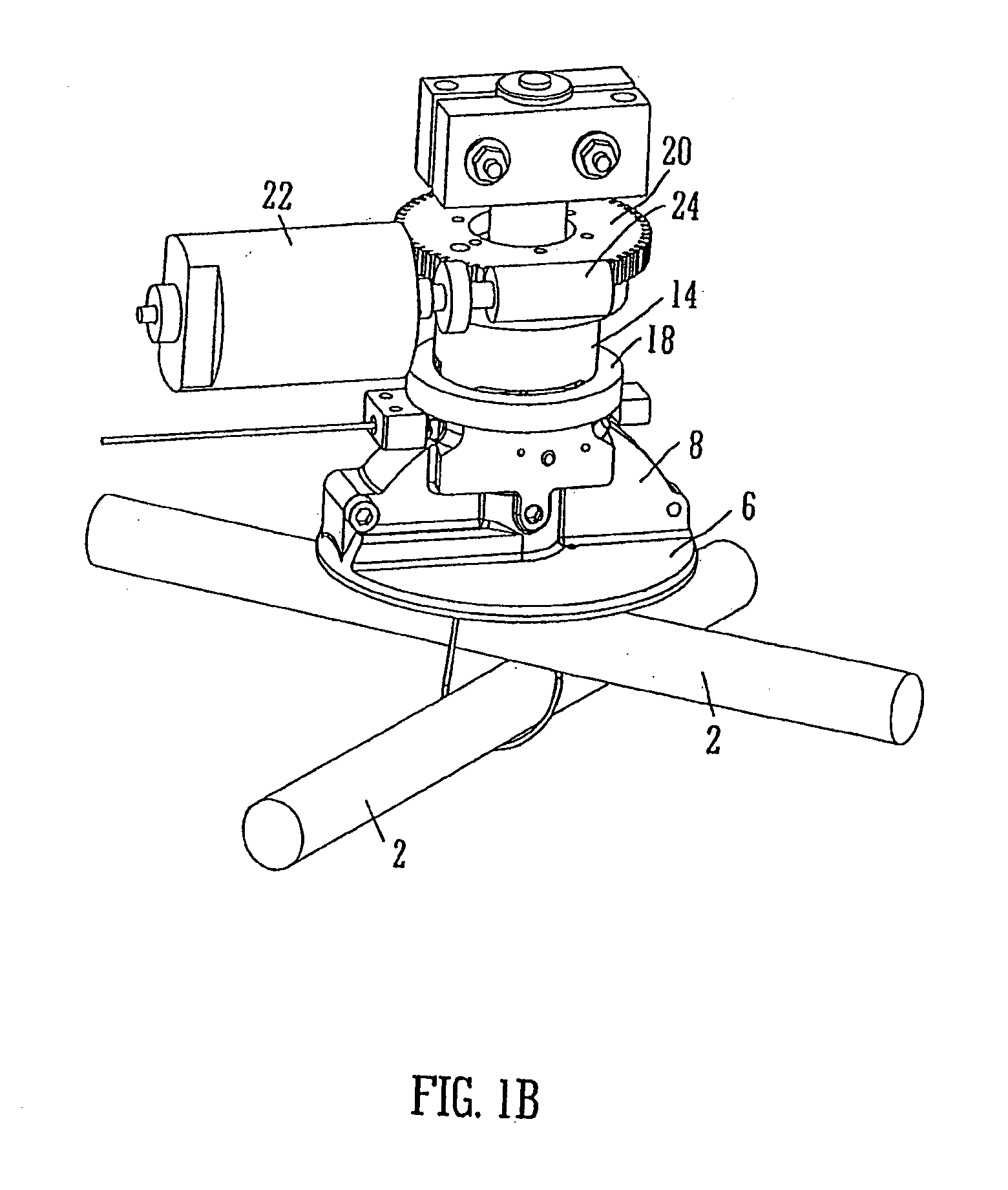
[0023]Referring first to FIGS. 1a, 1b and 2 there are shown two perspective views and a sectional view of part of an apparatus in accordance with the invention with certain parts such as the housing, handle, battery, controls, lower shroud and wire spool removed for clarity. The apparatus is shown situated over a junction where two steel bars 2 cross over each other at right angles. The steel bars 2 are intended to form a rectangular grid to be embedded in a concrete structure in order to reinforce it.

[0024]Sitting in use above the uppermost bar 2 is the rotary head of the apparatus 4. This includes a horizontal circular base plate 6 extending up from which is a channel 8 which is approximately semi-circular in vertical section and of approximately constant width in the orthogonal direction. The underneath of the base plate 6 is shown in FIG. 3 from which it will be seen that on one side there is a narrow slot 10 corresponding to one end of the semi-circular channel and on the other...


PUM


Abstract

An apparatus for tying a wire around one or more objects such as concrete reinforcing bars is disclosed. It comprises means for passing the wire in a loop around the bars and a rotatable head for twisting the ends of the loop together. The head has at least one clamping member for clamping the wire. The clamping member provides a higher clamping force when tension in the wire is increases.

Description

BACKGROUND OF THE INVENTION[0001]1. Field of the Invention[0002]This application relates to machines for binding together concrete reinforcing bars using wire ties.[0003]One such machine is described in WO 2004 / 083559.[0004]2. Description of the Related Art[0005]A problem with known machines has been identified by the Applicant. To achieve the proper tension in the twisted wire known machines rely on the bending strength of the wire and friction exhibited between the wire and the gripping parts of the machine. However, if the surface of the wire or the interior gripping surface inside the machine should be contaminated with oil or grease, or indeed even if the machine is used in damp conditions, the degree of friction actually exhibited may be less than intended leading to a lower tension in the twisted wire and therefore a more loosely tied connection.SUMMARY OF THE INVENTION[0006]The present application aims to reduce this problem and provides a machine for tying a wire around a p...

Claims


Application Information

Patent Timeline
IPC IPC(8): B30B9/30
CPCE04G21/122E04G21/123
Inventor BARNES, GRAHAM FRANKCOLES, IAN DAVID
Owner TYMATIC
Learn More