
Process for increasing the yield of an isomerization zone fractionation

a technology of isomerization zone and fractionation, which is applied in the direction of hydrocarbon preparation catalysts, hydrocarbon by saturated bond conversion, organic chemistry, etc., can solve the problems of large fractionation columns, large recycle streams, and large utility costs, and achieve the effect of increasing the conversion rate of iso-paraffins in the isomerization zon

Active Publication Date: 2016-04-05
UOP LLC
View PDF17 Cites 2 Cited by
  • Summary
  • Abstract
  • Description
  • Claims
  • Application Information

AI Technical Summary

Benefits of technology

This approach increases the yield of normal paraffins per pass in the isomerization zone, reduces the production of low-value methane, and allows for more efficient processing with smaller equipment, resulting in lower capital and operating expenses.

Problems solved by technology

The composition of the feed to the steam cracking reactor affects the results.
Benzene and other aromatics are particularly resistant to steam cracking and undesirable as cracking feed stocks, with only the alkyl side chains being cracked to produce the desired product.
This variety results in it being very difficult to separate less desirable feed components, such as naphthenes and aromatics, from the feed stream by fractional distillation.
Based upon typical processing conditions, full conversion of the iso-paraffins entails large recycle streams, large fractionation columns, and large utility costs.
The cracking reactions can lead to the production of undesired low value methane.

Method used


Image

  • Process for increasing the yield of an isomerization zone fractionation
  • Process for increasing the yield of an isomerization zone fractionation
  • Process for increasing the yield of an isomerization zone fractionation

Examples


first embodiment

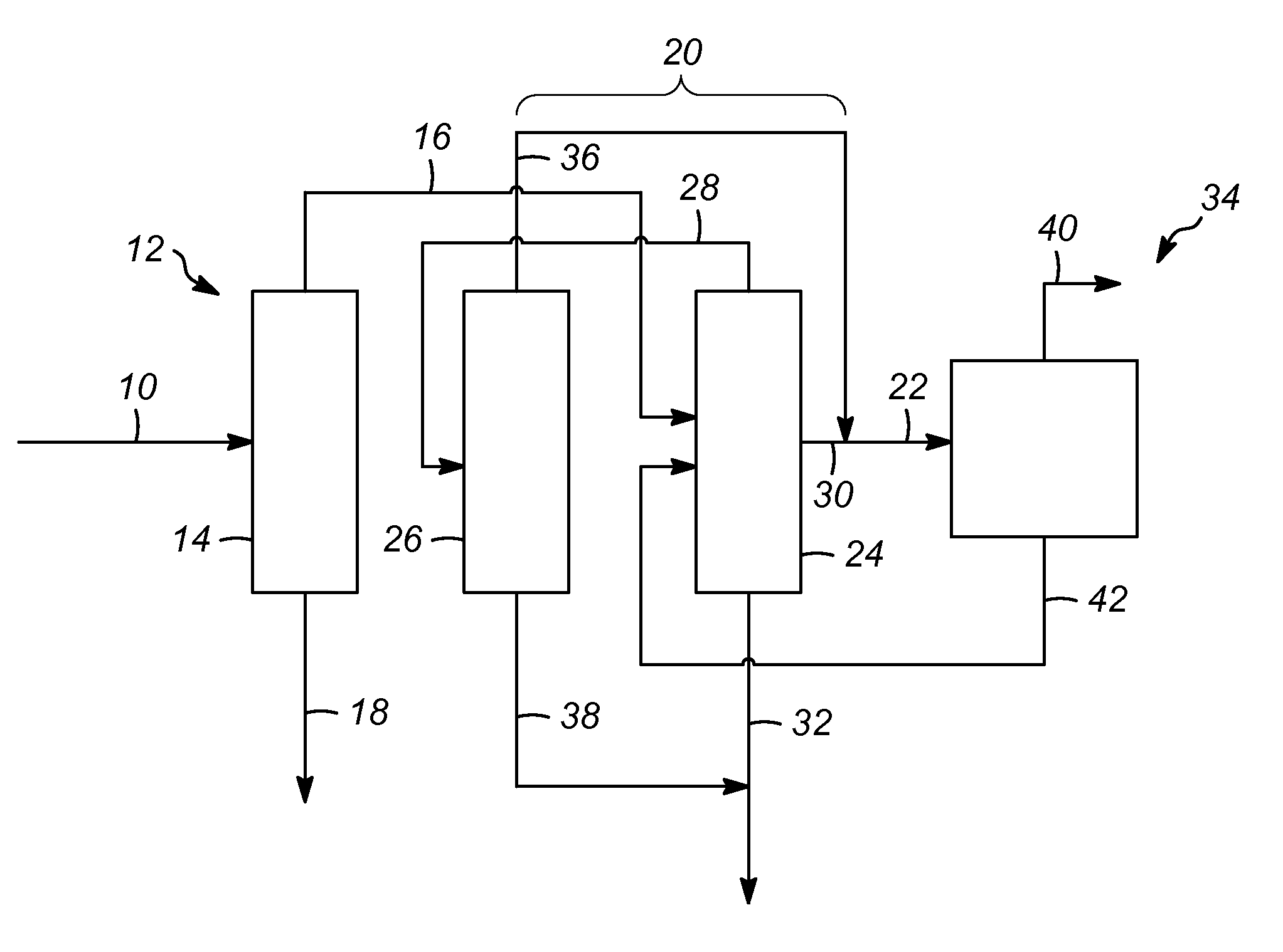
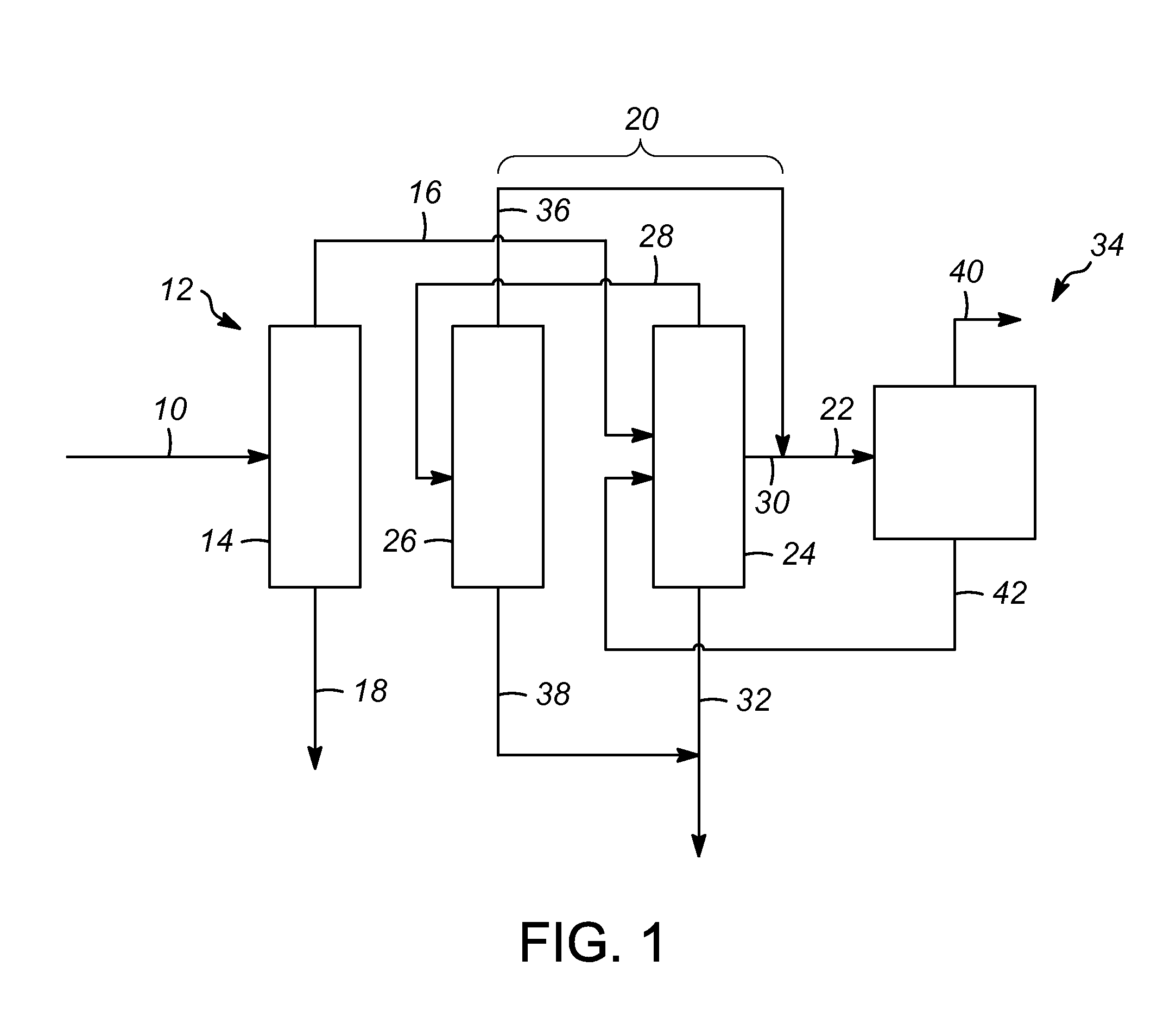
[0030]the present invention is shown in FIG. 1, in which a feed stream 10 is passed into a first separation zone 12. The feed stream 10 is preferably hydrotreated naphtha comprising C5+ hydrocarbons (meaning hydrocarbons having five or more carbon atoms).

[0031]The first separation zone 12 may include a separator column 14, such as a fractionation column. As will be appreciated, the depiction of column 14 is simplified as all the auxiliary operational components, such as controls, trays, condenser and reboiler, may be of conventional design. The feed stream 10, or multiple feed streams, can be fed into the column 14 at different locations if appropriate. The column 14 will typically contain conventional vapor-liquid contacting equipment such as trays or packing. The type of tray and design details such as tray type, tray spacing and layout may vary within the column 14.

[0032]The column 14 will separate the feed stream 10 into an overhead stream 16 and a bottoms stream 18. The overhea...

third embodiment

[0070]In a third embodiment according to the present invention as shown in FIG. 3, a feed stream 200 is passed into a first separation zone 202. The feed stream 200 is preferably hydrotreated naphtha comprising C5+ hydrocarbons.

[0071]The first separation zone 202 may also include a separator column 204, such as a fractionation column. This column 204 will separate the feed stream 200 into an overhead stream 206, an intermediate stream 208, and a bottom stream 210. The overhead stream 206 may comprise C5 hydrocarbons and iC6 hydrocarbons. The intermediate stream 208 may comprise n-hexane and C6 cyclic hydrocarbons. The bottoms stream 210 may comprise C7+ hydrocarbons. The bottoms stream 210 may be passed to various other zones, such as, for example: to saturation and then to a steam cracker; to a reformer and then to an aromatic complex; to saturation, then to a ring operating reactor, and then to a steam cracker; or a combination of the foregoing. The further processing of bottoms s...


PUM

PropertyMeasurementUnit
boiling pointaaaaaaaaaa
operating pressuresaaaaaaaaaa

Abstract

A process for increasing a yield of an isomerization zone by removing at least a portion of the C6 cyclic hydrocarbons from a stream prior to it being passed into the isomerization zone. Additionally, disproportionation reactions occur producing valuable C3 hydrocarbons and C4 hydrocarbons. Also, a higher ring opening conversion of C5 cyclic hydrocarbons is observed.

Description

FIELD OF THE INVENTION[0001]This invention relates to processes for separating out various fractions of a naphtha stream to increase a yield of normal paraffins in an isomerization zone.BACKGROUND OF THE INVENTION[0002]Ethylene and propylene are important chemicals for use in the production of other useful materials, such as polyethylene and polypropylene. Polyethylene and polypropylene are two of the most common plastics found in use today and have a wide variety of uses for, for example, a material for fabrication and as a material for packaging. Other uses for ethylene and propylene include the production of vinyl chloride, ethylene oxide, ethylbenzene and alcohol.[0003]The great bulk of the ethylene consumed in the production of the plastics and petrochemicals such as polyethylene is produced by the thermal cracking of higher molecular weight hydrocarbons. Steam is usually mixed with the feed stream to the cracking reactor to reduce the hydrocarbon partial pressure and enhance o...

Claims


Application Information

Patent Timeline
Patent Type & Authority Patents(United States)
IPC IPC(8): C07C5/27C07C5/00C07C7/00C07C6/08
CPCC07C7/005C07C5/00C07C5/27C07C4/06C07C5/2754C07C6/123C07C7/04C07C7/13C10G45/62C07C2521/04C07C2523/42C10G2300/1044C10G2300/1081C07C5/2724C07C9/08C07C9/10C07C9/12C07C9/14C07C9/16C07C9/18
Inventor LAPINSKI, MARK P.LIPPMANN, MATTHEWFUNK, GREGORYSHECTERLE, DAVID JAMESMOKKA, LAKSHMI P.
Owner UOP LLC
Learn More