
Cooling system for high average power laser

a laser and high average power technology, applied in the field of cryogenically cooling, can solve the problems of limiting the average power of these amplifiers, deteriorating beam quality, and large deformations in the laser material, and achieve the effect of reducing heat transfer efficiency and superior properties

Active Publication Date: 2015-12-08
COLORADO STATE UNIVERSITY
View PDF13 Cites 10 Cited by
  • Summary
  • Abstract
  • Description
  • Claims
  • Application Information

AI Technical Summary

Benefits of technology

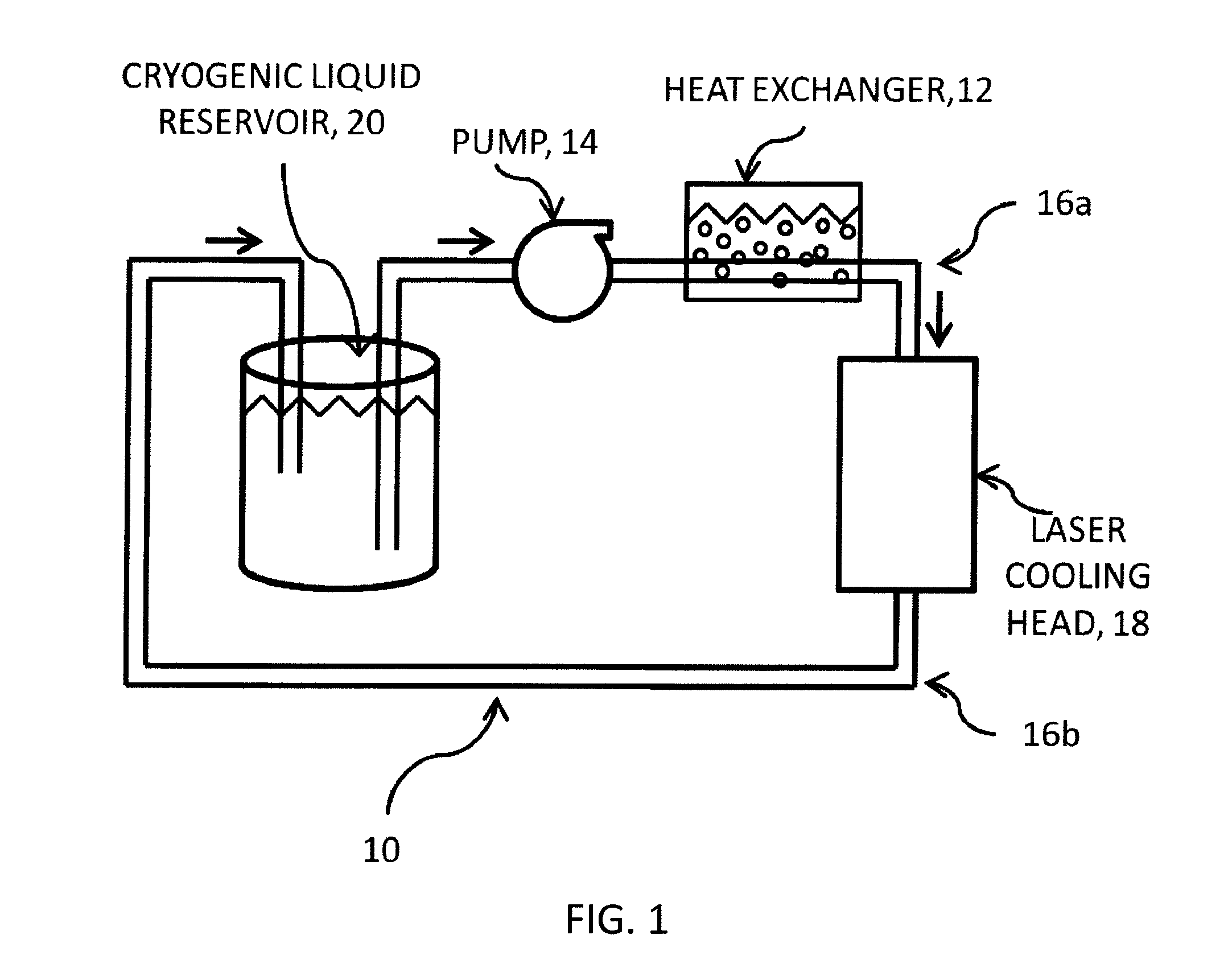
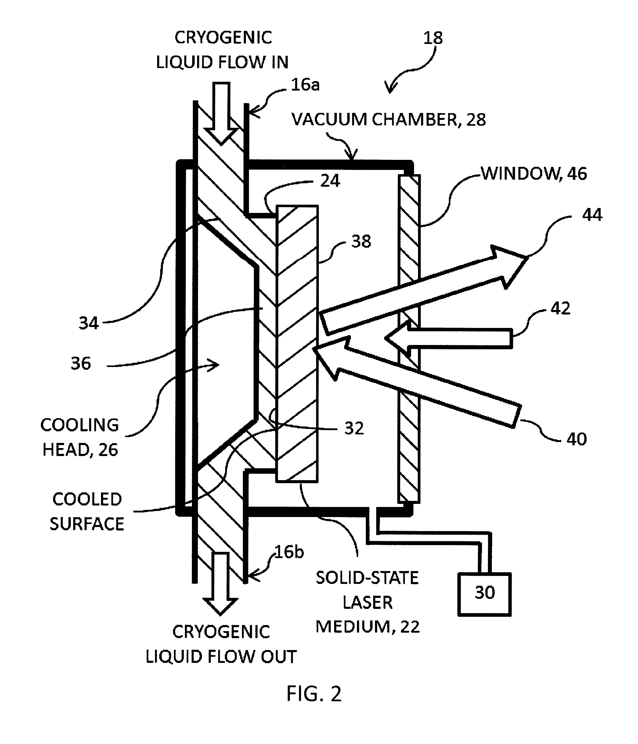
The present invention provides a way to cool down solid-state laser amplifier material using cryogenics, which has advantages at low temperatures such as better performance. The method also prevents the formation of bubbles on the surface of the material, which can reduce heat transfer efficiency.

Problems solved by technology

A portion of the pump energy is locally converted to heat within the material, thereby limiting average power of these amplifiers as a result of the onset of thermal effects due to thermal gradients within the amplifier material, such as thermal lensing, thermal birefringence or, in some materials, a reduction of gain from excessive heating.
For large area disks required for high-energy amplifiers, the mismatch in thermal expansion between the laser material and heat sink may result in large deformations in the laser material when cooled to cryogenic temperatures in a similar manner to that for bimetallic materials.
Such deformations cause deterioration of beam quality, which is unacceptable for most applications.
Additionally, the use of any material between the laser material and the cooling source results in an increase in temperature due to conduction within the heat sink.
However, the maximum heat power flux that can be dissipated through this technique is limited by the transition from the nucleate boiling regime to the film boiling regime.
As the thermal flux is increased, a thin layer of vapor may form over the interface effectively shielding the solid surface from the liquid coolant, and significantly reducing heat transfer efficiency.
The critical heat flux of liquid nitrogen at atmospheric pressure is about 20 W / cm2, which limits the average power of such laser amplifiers.

Method used


Image

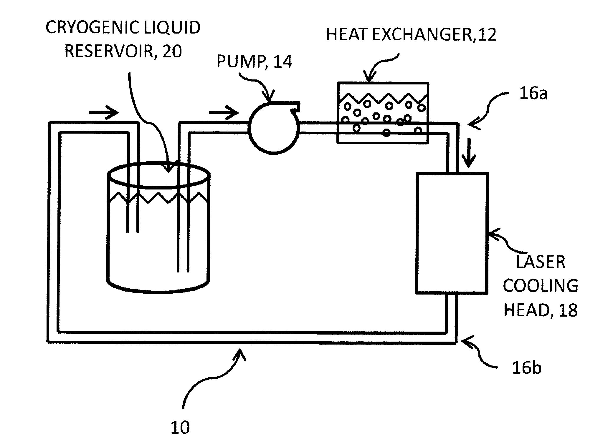
  • Cooling system for high average power laser
  • Cooling system for high average power laser
  • Cooling system for high average power laser

Examples


example

[0028]FIG. 3 is a schematic representation of high-energy, all-diode-pumped, chirped pulse amplification system, 46, that produces Joule-level pulses at high repetition rates (100 Hz) in which liquid oxygen cooled, Yb:YAG laser power amplifier, 48, has been employed. Laser system 46 includes diode-pumped, mode-locked Yb:KYW oscillator, 50, grating pulse stretcher, 52, three stages of amplification, 54, 56, and 48, and pulse compressor, 58. Amplifier 54 is a room temperature Yb:YAG regenerative amplifier that amplifies the stretched seed pulses from oscillator 50 to the millijoule level. Amplifiers 56 and 48 are cryogenically-cooled Yb:YAG amplifiers. The use of a broad bandwidth room temperature Yb:YAG preamplifier combined with cryogenic power amplifiers permits exploitation of the high power characteristics of Yb:YAG at cryogenic temperatures without excessive gain narrowing in the preamplifier. The thick-disk active mirror second stage of amplification was used to amplify the pul...


PUM


Abstract

A cryogenic cooling apparatus for high average power laser oscillator or amplifier, wherein the oscillator or amplifier material is in direct contact with a flowing cryogenic liquid cooled to below its boiling point is described. This method of cooling overcomes the limit in heat flux due to the onset of film boiling, thereby allowing for increased laser average power.

Description

RELATED CASES[0001]The present patent application claims the benefit of Provisional Patent Application Ser. No. 61 / 570,415 filed on 14 Dec. 2011 entitled “High Energy High Power Laser Amplifier” by Brendan A; Reagan et al., the disclosure and teachings of which are hereby incorporated by reference herein.STATEMENT REGARDING FEDERAL RIGHTS[0002]This invention was made with government support under Grant No. EEC0310717 awarded by the National Science Foundation. The government has certain rights in the invention.FIELD OF THE INVENTION[0003]The present invention relates generally to laser oscillators and amplifiers and, more particularly, to cryogenically-cooled, high average power laser oscillators and amplifiers.BACKGROUND OF THE INVENTION[0004]There is significant interest in developing high pulse energy (Joules) and high average power diode-pumped solid state lasers for applications where a low energy laser pulse is amplified by one or more amplifiers to achieve high pulse energy. ...

Claims


Application Information

Patent Timeline
IPC IPC(8): H01S3/04H01S5/024H01L23/34
CPCH01S5/024H01S3/0407H01L23/34H01S5/02407H01S3/0621H01S3/1618H01S3/2316H01S3/2341H01S3/027H01S3/042H01S3/0604H01S3/1643H01L2924/0002H01S3/0813H01L2924/00
Inventor REAGAN, BRENDAN A.ROCCA, JORGE J.WERNSING, KEITH A.CURTIS, ALDEN H.FURCH, FEDERICO J.
Owner COLORADO STATE UNIVERSITY
Learn More