
Electrode assembly and method for constructing the same

a technology of electrode electrode and assembly method, which is applied in the manufacture of final products, cell components, wound/folded electrode electrodes, etc., can solve problems such as defects, and achieve the effect of high thermal stability and good heat resistance of the battery

Active Publication Date: 2015-11-03
LG ENERGY SOLUTION LTD
View PDF33 Cites 4 Cited by
  • Summary
  • Abstract
  • Description
  • Claims
  • Application Information

AI Technical Summary

Benefits of technology

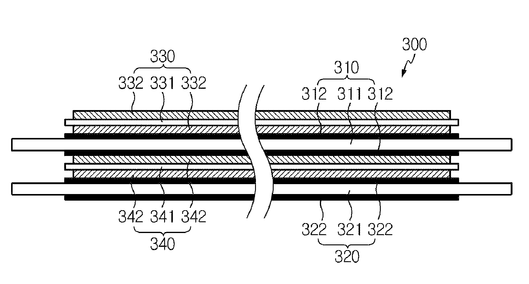
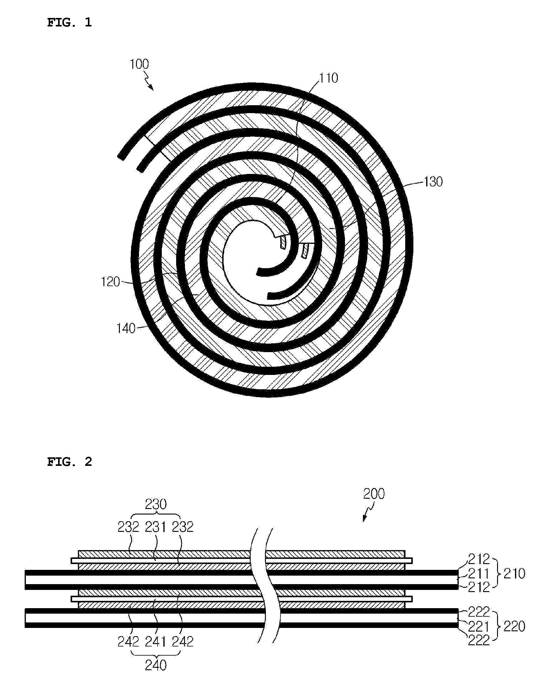
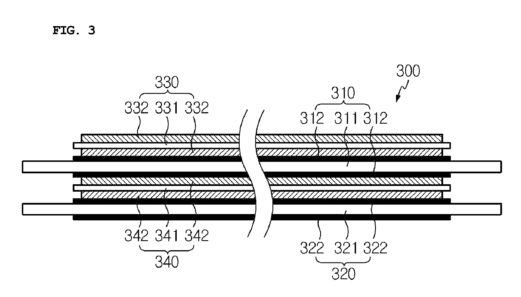
The present invention relates to a new design for an electrode assembly in a battery. The design includes separators with special coatings that have excellent resistance to heat. These coatings are only present where the separators touch the anode and cathode. This prevents the coatings from separating during winding or when a mandrel is withdrawn. The design also prevents poor winding caused by different friction characteristics. The coatings are blocked from sticking to the outer surface of the assembly, so they cannot be separated from the separators. This prevents the coatings from being separated during the process of adhering a tape to the assembly. Overall, this design improves the thermal stability of the battery and ensures high performance.

Problems solved by technology

However, when a mandrel is withdrawn or the separator is cut after winding in the course of the fabrication of an electrochemical device, defects may be caused.

Method used


Image

  • Electrode assembly and method for constructing the same
  • Electrode assembly and method for constructing the same
  • Electrode assembly and method for constructing the same

Examples


example 1

Separator Having Porous Coating Layer Formed at One Surface Thereof

[0056]Polyvinylidene fluoride-co-chlorotrifluoroethylene (PVdF-CTFE) and cyanoethylpullulan in a weight ratio of 10:2 were added to and dissolved in acetone at 50° C. for about 12 hr. To the polymer solution was added Al2O3 powder in such an amount that the weight ratio of the polymers to the inorganic particles was 5:95. The inorganic particles were crushed and dispersed in the solution by ball milling for at least 12 hr to prepare a slurry. The inorganic particles of the slurry had an average particle size of 600 nm.

[0057]The slurry was coated to a thickness of 4μm on one surface of a 12 μm thick porous polyolefin membrane (porosity 40%) using a slot die coater. For intermittent coating, the amount of the slurry supplied was controlled such that about 90 mm long uncoated portions were formed on both ends of the porous membrane.

[0058]Subsequently, the coated substrate was passed through a drier whose temperature was...

example 2

Separator Having Porous Coating Layers Formed at Both Surfaces Thereof

[0059]A slurry was prepared in the same manner as in Example 1. The slurry was coated to thicknesses of 2 μm on both surfaces of a 12 μm thick porous polyolefin membrane (porosity 40%) using a dip coater. For intermittent coating of the slurry, a knife was allowed to come into periodic contact with the surfaces of the porous membrane such that about 90 mm long uncoated portions were formed on both ends of the porous membrane.

[0060]Subsequently, the coated substrate was passed through a drier whose temperature was set to 50° C. to remove the solvent, completing the production of a separator. The bonding strength between the porous polyethylene membrane and the coating layers was as low as 15 gf / cm. Despite the low bonding strength, the inorganic particles did not fall off from the coating layers in the course of the fabrication of a cylindrical battery including holding the uncoated portions of the separator by a m...


PUM

PropertyMeasurementUnit
dielectric constantaaaaaaaaaa
temperaturesaaaaaaaaaa
particle sizeaaaaaaaaaa

Abstract

A jelly-roll type electrode assembly is disclosed. The jelly-roll type electrode assembly includes an anode, a cathode, and separators interposed between the anode and the cathode and having a greater length than width. Each of the separators is longer than the anode and the cathode. Each of the separators has a porous substrate and porous coating layers formed on both surfaces of the porous substrate. The porous coating layers include a mixture of inorganic particles and a binder polymer. The porous coating layers are formed only in areas where the separators are in contact with the anode and the cathode. The porous coating layers enhance the heat resistance of the separators. Due to the enhanced heat resistance, the separators can prevent the performance of a battery from deteriorating. In addition, the porous coating layers can be prevented from being separated from the separators during battery assembly processing.

Description

CROSS-REFERENCE TO RELATED APPLICATION[0001]This application is a continuation of International Application No. PCT / KR2011 / 008514 filed on Nov. 9, 2011, which claims priorities to Korean Patent Application No. 10-2011-0025851 filed in the Republic of Korea on Mar. 23, 2011, the entire contents of which are incorporated herein by reference.TECHNICAL FIELD[0002]The present disclosure relates to an electrode assembly for a secondary battery and a method for constructing the electrode assembly. More specifically, the present disclosure relates to an electrode assembly for a secondary battery which uses separators with porous coating layers to achieve improved heat resistance.BACKGROUND ART[0003]Recently, there has been growing interest in energy storage technologies. As the application fields of energy storage technologies have been extended to mobile phones, camcorders, notebook computers and even electric cars, efforts have increasingly been made towards the research and development o...

Claims


Application Information

Patent Timeline
Patent Type & Authority Patents(United States)
IPC IPC(8): H01M2/16H01M2/14H01M50/406
CPCH01M2/166H01M2/145Y10T29/49115Y02E60/10H01M50/446Y02P70/50H01M50/406H01M10/0431H01M50/449H01M50/403H01M50/411
Inventor LEE, JOO-SUNGKIM, JONG-HUNRYU, BO-KYUNG
Owner LG ENERGY SOLUTION LTD
Learn More