Dose rate measurement system
a dose rate and measurement system technology, applied in the field of radiation dose rate measurement system, can solve the problems of deterioration of the original energy characteristics of the low range dose rate, error caused by the energy characteristics of the high dose rate range and the level difference generated, etc., and achieve high dose rate, high accuracy, good energy characteristics
- Summary
- Abstract
- Description
- Claims
- Application Information
AI Technical Summary
Benefits of technology
Problems solved by technology
Method used
Image
Examples
first embodiment
[0021]FIG. 1 is a diagram showing the configuration of a dose rate measurement system according to a first embodiment.
[0022]As shown in FIG. 1, a dose rate measurement system 1 is composed of: a radiation detector 2 which absorbs incident radiation energy, and sends a discrete current pulse having electric charge proportional to the absorbed energy and a DC voltage in which a DC current proportional to the absorbed radiation energy is converted; a high voltage power source 4 which supplies a high voltage that operates the radiation detector 2; and measurement unit 3 in which the current pulse and the DC voltage are applied from the radiation detector 2 to be converted to a low range dose rate and a high range dose rate respectively, and the low range dose rate and the high range dose rate are switched to be sent depending on the dose rates.
[0023]Next, the configuration and operation of the measurement unit 3 of the dose rate measurement system 1 will be described in detail. As shown...
second embodiment
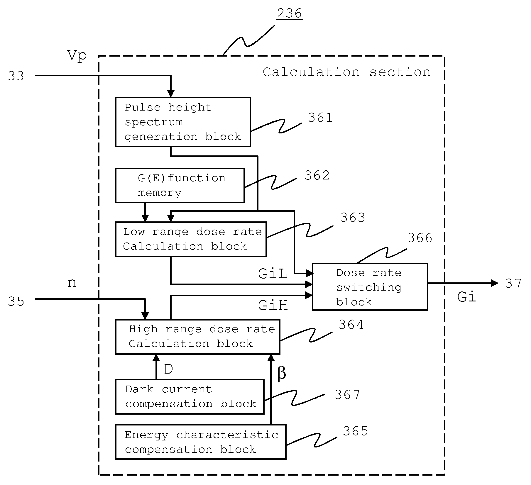
[0037]FIG. 4 is a diagram showing the configuration of a calculation section of a dose rate measurement system according to a second embodiment. A different point from the calculation section 36 of the dose rate measurement system 1 of the first embodiment is that a calculation section 236 of the second embodiment is provided with a dark current compensation block 367 as means of compensating dark current, by which the dark current of a radiation detector 2 at a high range dose rate in a high range dose rate calculation block 364 is compensated; and other constitutional elements are similar to the first embodiment and their description will be omitted.
[0038]Next, the operation of the dark current compensation block 367 will be described. The dark current compensation block 367 stores a dose rate D which is to be compensated corresponding to an average dark current Id of the radiation detector 2 at a reference temperature K0, the dose rate D being preliminarily set and applied from t...
third embodiment
[0040]FIG. 5 is a diagram showing the configuration of a dose rate measurement system according to a third embodiment. FIG. 6 is a diagram showing the temperature characteristics of dark current of a radiation detector in the third embodiment. A different point from the dose rate measurement system 1 of the first embodiment is that: a dose rate measurement system 10 of the third embodiment is provided with a temperature sensor 5 that measures the temperature of a radiation detector 2; a dose rate of the dark current dependent on the temperature of the radiation detector 2 is calculated by a dark current temperature compensation block 368 based on temperature sent from the temperature sensor 5, the dark current temperature compensation block 368 being provided as means of compensating dark current temperature in the calculation section 336 of the measurement unit 30; and compensation is performed such that the high range dose rate calculation block 364 subtracts the dose rate of the ...
PUM
 Abstract
Description
Claims
Application Information
 - R&D
- Intellectual Property
- Life Sciences
- Materials
- Tech Scout
- Unparalleled Data Quality
- Higher Quality Content
- 60% Fewer Hallucinations
Browse by: Latest US Patents, China's latest patents, Technical Efficacy Thesaurus, Application Domain, Technology Topic, Popular Technical Reports.
© 2025 PatSnap. All rights reserved.Legal|Privacy policy|Modern Slavery Act Transparency Statement|Sitemap|About US| Contact US: help@patsnap.com


