Rotor phase/speed estimating device for an AC motor

a technology of ac motor and estimating device, which is applied in the direction of electronic commutators, dynamo-electric converter control, dynamo-electric gear control, etc., can solve the problems of unstable estimation system, difficult to introduce a filter for separation, and inability to use this kind of position/speed sensor, etc., to achieve the effect of minimizing loss, minimizing operation load and minimizing loss

Active Publication Date: 2015-06-02
NIDEC CORP
View PDF19 Cites 0 Cited by
  • Summary
  • Abstract
  • Description
  • Claims
  • Application Information

AI Technical Summary

Benefits of technology

[0030](1) to provide a rotor phase / speed estimating device which does not require any dynamic processing for separating and detecting a high-frequency current from a stator current, which does not need any narrow bandpass filter arranged to accurately detect only a high-frequency component, which can achieve high stability in principle and which does not involve any phase lag or phase advance;
[0031](2) to provide a rotor phase / speed estimating device which can generate a correlation signal capable of having a broad positive correlation region and which is less susceptible to estimation instability otherwise caused by sudden disturbance; and
[0032](3) to provide a rotor phase / speed estimating device which can use a simple high-frequency voltage injection device and which can be realized with ease.

Problems solved by technology

However, the use of this kind of position / speed sensor is not desirable from the view point of reliability, axial volume, sensor cable arrangement, and cost.
However, if the stable operation of an estimating system is taken into account, it is not necessarily easy to introduce a filter for separation and detection of the high-frequency current into the estimating system.
However, the narrow bandwidth tends to make the estimating system unstable.
This makes it difficult to perform estimation with increased accuracy.
Thus, a great deal of time and effort is needed in appropriately designing the bandpass filter (see Y. Chen, L. Wang and L. Kong: “Research of Position Sensor-less Control of PMSM Based on High Frequency Signal Injection”, Proc.
Moreover, each time when the high frequency of the high-frequency voltage injected is changed, it is necessary to redesign the bandpass filter through another time-consuming trial-and-error method (see Y. Chen, L. Wang and L. Kong: “Research of Position Sensor-less Control of PMSM Based on High Frequency Signal Injection”, Proc.
If the highpass filter is used in separating and detecting the high-frequency current, it is usual that the detected high-frequency current undergoes a phase advance due to unavoidable properties of the highpass filter.
This phase advance makes it difficult to correctly perform phase estimation.
This makes it difficult to perform estimation with increased accuracy.
It is usually impossible to come back to stable estimation once the estimating system fails to perform stable estimation.
However, the prior inventions require a troublesome high-frequency voltage injection means as is noted in Japanese Patent Application Publication No. 2009-171680, Japanese Patent Application Publication No. 2007-185080, Japanese Patent Application Publication No. 2009-171680, Japanese Patent Application Publication No. 2009-273254, and Japanese Patent Application Publication No. 2009-273283, describing that “a rectangular-wave alternating high-frequency voltage consisting of two pulse voltages equal in amplitude and pulse width to each other but differing in polarity from each other is applied to a motor in a plurality of vector directions”.

Method used


Image

  • Rotor phase/speed estimating device for an AC motor
  • Rotor phase/speed estimating device for an AC motor
  • Rotor phase/speed estimating device for an AC motor

Examples


first preferred embodiment

[0116]FIG. 5 shows a first preferred embodiment of the phase / speed estimator 10. The phase / speed estimator 10 preferably includes four devices, namely a high-frequency voltage command generator (HFVC) 10-1 arranged to provide a high-frequency voltage injection device, a high-frequency amplitude detector of a fundamental component 10-2 arranged to provide a high-frequency current amplitude detection device of a fundamental wave component, a correlation signal generator 10-3 arranged to provide a correlation signal generation device and a phase synchronizer 10-4 arranged to provide a rotor phase generation device.

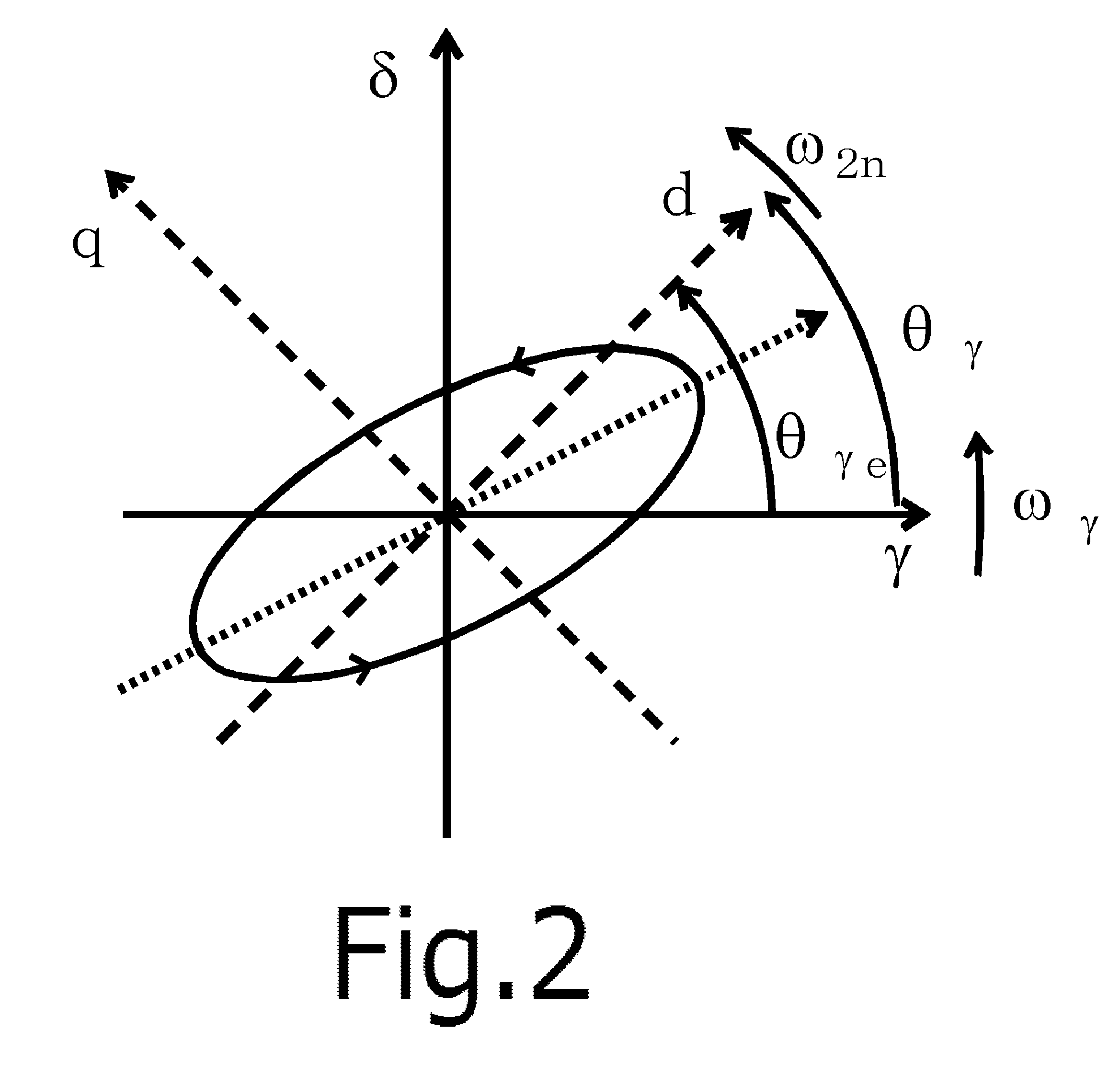
[0117]The high-frequency voltage command generator 10-1 is arranged to generate a high-frequency voltage target value on a dual-axis orthogonal γ-δ semi-synchronous coordinate system in which the rotor phase estimated value is used as a base axis (γ axis) phase. As shown in FIG. 4, the high-frequency voltage command generator 10-1 performs a high-frequency voltage injection t...

second preferred embodiment

[0123]FIG. 6 shows a second preferred embodiment of the present invention. Major components making up the stator current preferably include a drive current of zero frequency and a high-frequency current fundamental wave component. The amplitude of the high-frequency current fundamental wave component is detected by the high-frequency amplitude detector of a fundamental component 10-2. The detection accuracy of the high-frequency current fundamental wave component amplitude can be increased by removing beforehand the major components not to be detected. The preferred embodiment shown in FIG. 6 is based on this point of view. The only difference between the preferred embodiments shown in FIGS. 6 and 5 lies in the signal inputted to the high-frequency amplitude detector of a fundamental component 10-2. Other points remain the same.

[0124]The high-frequency amplitude detector of a fundamental component 10-2 of the preferred embodiment shown in FIG. 6 is configured to detect a primary Fou...

third preferred embodiment

[0125]FIG. 7 shows a third preferred embodiment according to the present invention. The only difference between the preferred embodiments shown in FIGS. 7 and 5 lies in the signal inputted to the high-frequency amplitude detector of a fundamental component 10-2. Other points remain the same. In the preferred embodiment shown in FIG. 7, from the same viewpoint as in the preferred embodiment shown in FIG. 6, a DC component is removed from the signal inputted to the high-frequency amplitude detector of a fundamental component 10-2. The DC cut filter 10-6 is used in removing the DC component. The DC cut filter 10-6 can be replaced by a bandpass filter or a highpass filer having a more-than-enough broad bandwidth. The employment of the filer having a more-than-enough broad bandwidth does not adversely affect the stability of a phase estimating system.

[0126]The high-frequency amplitude detector of a fundamental component 10-2 of the preferred embodiment shown in FIG. 7 is configured to de...


PUM


Abstract

A rotor phase / speed estimating device includes a high-frequency voltage injection unit, a high-frequency current amplitude detection unit of a fundamental wave component, a correlation signal generation unit, and a rotor phase generation unit. The high-frequency voltage injection unit applies a high-frequency voltage to an AC motor. The high-frequency current amplitude detection unit of a fundamental wave component detects a primary Fourier coefficient equivalent value. The correlation signal generation unit is arranged to generate a correlation signal using the Fourier coefficient equivalent value. The rotor phase generation unit is arranged to generate an estimated value of the rotor phase and an estimated value of a rotor speed using the correlation signal.

Description

BACKGROUND OF THE INVENTION[0001]1. Field of the Invention[0002]The present invention relates to a rotor phase / speed estimating device that estimates a phase (i.e., a position) and a speed of a rotor without having to use a position / speed sensor (i.e., in a sensor-less manner). The rotor phase / speed estimating device is preferably used in a drive control device in an AC motor in which a rotor shows a salient pole characteristic with respect to a high-frequency current having a frequency higher than a drive frequency (e.g., a permanent-magnet synchronous motor including a permanent magnet arranged in a rotor, a wound-rotor type synchronous motor, a synchronous reluctance motor, a hybrid field-magnet type synchronous motor including a permanent magnet and a field winding arranged in a rotor, an induction motor, etc.).[0003]2. Description of the Related Art[0004]High-performance control of an AC motor can be achieved by a so-called vector control method. Information on a phase of a rot...

Claims


Application Information

Patent Timeline
Patent Type & Authority Patents(United States)
IPC IPC(8): G01P3/42H02P6/06H02P27/04H02P6/08H02P6/16H02P6/182H02P6/28H02P21/00H02P21/14H02P21/18H02P21/22H02P21/24H02P21/28H02P23/16H02P25/026H02P27/08
CPCH02P21/146H02P21/0042H02P2203/11H02P21/26H02P21/18
Inventor SHINNAKA, SHINJI
Owner NIDEC CORP
Why Eureka
Try Eureka