Gasification quench chamber and scrubber assembly

a technology of gasification quench chamber and scrubber, which is applied in the direction of muffling furnaces, furnaces, lighting and heating apparatus, etc., can solve the problems of operating problems, excess liquid carried from the quench chamber and into downstream equipment, etc., and achieve the effect of reducing the fluctuation and sloshing of coolant levels

Active Publication Date: 2015-05-12
AIR PROD & CHEM INC
View PDF13 Cites 4 Cited by
  • Summary
  • Abstract
  • Description
  • Claims
  • Application Information

AI Technical Summary

Benefits of technology

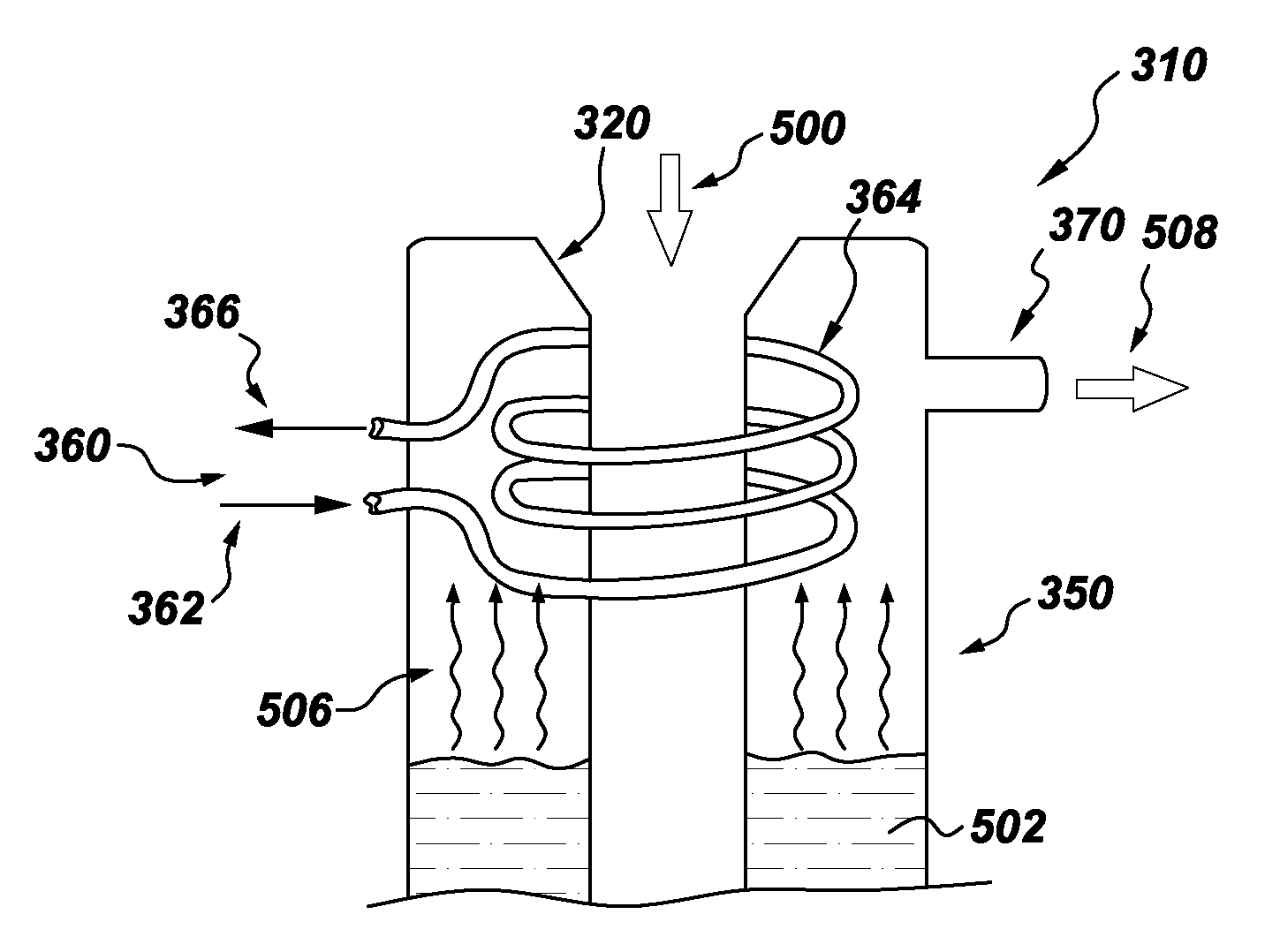
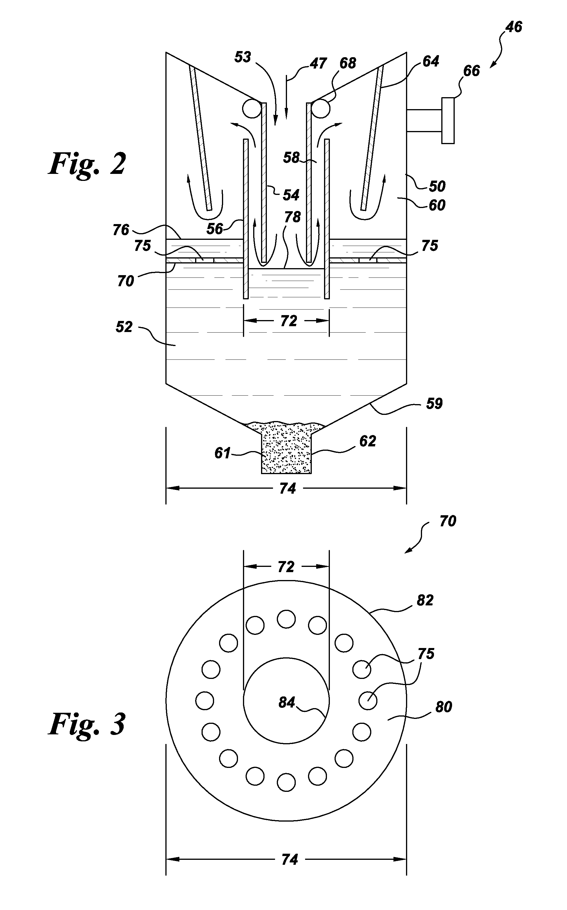
[0008]In accordance with one exemplary embodiment of the present invention, a gasification quench chamber comprises a reservoir having a liquid coolant disposed in a lower portion therein and an upper portion comprising an exit for exiting a cooled syngas therefrom; a dip tube configured to introduce a syngas mixture to contact the liquid coolant thereby producing the cooled syngas; a cooling device configured to further cool the cooled syngas in the upper portion; and a stability device in the lower portion, configured to mitigate coolant level fluctuation and sloshing.

Problems solved by technology

However, excessive liquid carried from the quench chamber and into downstream equipment, is found to pose operational problems.

Method used


Image

  • Gasification quench chamber and scrubber assembly
  • Gasification quench chamber and scrubber assembly
  • Gasification quench chamber and scrubber assembly

Examples


Embodiment Construction

[0021]One or more specific embodiments of the present invention will be described below. In an effort to provide a concise description of these embodiments, all features of an actual implementation may not be described in the specification. It should be appreciated that in the development of any such actual implementation, as in any engineering or design project, numerous implementation-specific decisions must be made to achieve the developers' specific goals, such as compliance with system-related and business-related constraints, which may vary from one implementation to another. Moreover, it should be appreciated that such a development effort might be complex and time consuming, but would nevertheless be a routine undertaking of design, fabrication, and manufacture for those of ordinary skill having the benefit of this disclosure.

[0022]When introducing elements of various embodiments of the present invention, the articles “a,”“an,”“the,” and “said” are intended to mean that ther...


PUM

PropertyMeasurementUnit
distanceaaaaaaaaaa
stabilityaaaaaaaaaa
temperaturesaaaaaaaaaa

Abstract

A gasification quench chamber is disclosed. The gasification quench chamber includes a reservoir that contains liquid coolant in its lower portion and an exit for the cooled syngas in its upper portion; a dip tube that is configured to introduce a syngas mixture to contact the liquid coolant which produces the cooled syngas; a cooling device configured to further cool the cooled syngas in its upper portion; and a stability device in the lower portion that is configured to mitigate coolant level fluctuation and sloshing. In an embodiment of the quench chamber, the cooling device includes a heat exchanger pipe. A quench chamber and scrubber assembly is also disclosed.

Description

CROSS-REFERENCE TO RELATED PATENT APPLICATIONS[0001]This application is a Continuation in Part, claiming priority to U.S. patent application Ser. No. 12 / 495,439, entitled “GASIFICATION SYSTEM FLOW DAMPING”, filed on Jun. 30, 2009, which is hereby incorporated by reference.[0002]This application is also a Continuation in Part, claiming priority to now abandoned U.S. patent application Ser. No. 12 / 494,385, entitled “QUENCH CHAMBER ASSEMBLY FOR A GASIFIER”, filed on Jun. 30, 2009, which is hereby incorporated by reference.BACKGROUND[0003]The invention relates generally to gasifiers, and more particularly to a gasification quench chamber and scrubber assembly.[0004]In a normal coal gasification process, wherein a particulated carbonaceous fuel such as coal or coke or a carbonaceous gas is burned, the process is carried out at relatively hot temperatures and high pressures in a combustion chamber. When injected fuel is burned or partially burned in the combustion chamber, an effluent is ...

Claims


Application Information

Patent Timeline
Patent Type & Authority Patents(United States)
IPC IPC(8): B01J7/00C10J1/207C10J3/48C10J3/74C10J3/76C10J3/84
CPCC10J3/84C10J3/845C10J3/485C10J3/74C10J3/76Y02E20/18C10J2300/0959C10J2300/0976C10J2300/1671Y02P20/129C10J3/82C10K1/08F25J1/00
Inventor TIWARI, PRASHANTAVAGLIANO, AARONCORRY, JUDETH BRANNONDINU, CONSTANTINKLOCKOW, HELGE BURGHARD HERWIGLASKOWSKI, GREGORY MICHAELMONAHAN, SARAH MARIERICO, DENISE MARIESTOREY, JAMES MICHAEL
Owner AIR PROD & CHEM INC
Why Eureka
Try Eureka