In-situ electric heating desorption remediation technology and device for contaminated sites

An electric heating and site technology, applied in the field of soil remediation, can solve the problems of high energy consumption, inability to effectively and stably control the heating temperature of polluted areas, and easy damage of heating pipes, etc., achieving a high degree of automation, energy saving, safety, stability, and guarantee. The effect of the repair effect

Active Publication Date: 2019-01-29
SHANGHAI GREENMENT ENVIRONMENTAL TECH CO L
View PDF4 Cites 0 Cited by
  • Summary
  • Abstract
  • Description
  • Claims
  • Application Information

AI Technical Summary

Problems solved by technology

[0005] The purpose of the present invention is to provide an in-situ electric heating desorption restoration technology and its device for contaminated sites, which overcomes the high energy consumption of the existing in-situ electric heating desorption technology in site restoration applications, the heating tube is easily damaged, and it is difficult to The temperature in the heating area has good automatic feedback adjustment of the power supply intensity, and the heating temperature in the polluted area cannot be effectively and stably controlled. A kind of in-situ electric heating desorption technology and device that can be engineered and suitable for small and medium-sized polluted sites is proposed.

Method used


Image

  • In-situ electric heating desorption remediation technology and device for contaminated sites
  • In-situ electric heating desorption remediation technology and device for contaminated sites
  • In-situ electric heating desorption remediation technology and device for contaminated sites

Examples


Embodiment Construction

[0028] Below in conjunction with accompanying drawing, the present invention will be further described with specific embodiment: see Figure 1-6 ,

[0029] The in-situ electric heating desorption repair technology for polluted sites includes the following steps:

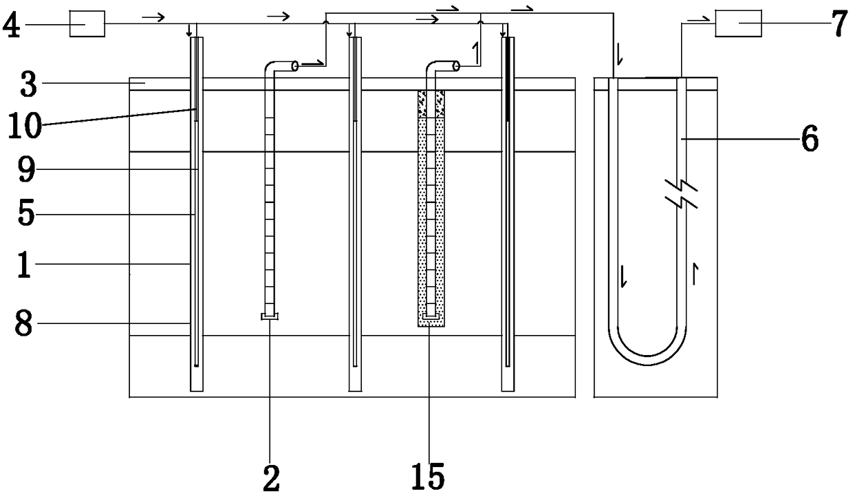
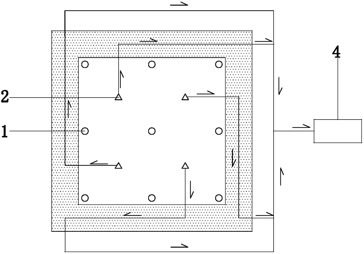
[0030] a. Insert several heating wells 1 and extraction wells 2 into the polluted site, the insertion depth is 1-4 meters;

[0031] b. Lay a thermal insulation layer 3 on the surface of the polluted site, and the thermal insulation layer is made of lightweight concrete;

[0032] c. Treat the groundwater in the polluted site as precipitation, and lower the groundwater to a position 5 meters below the ground;

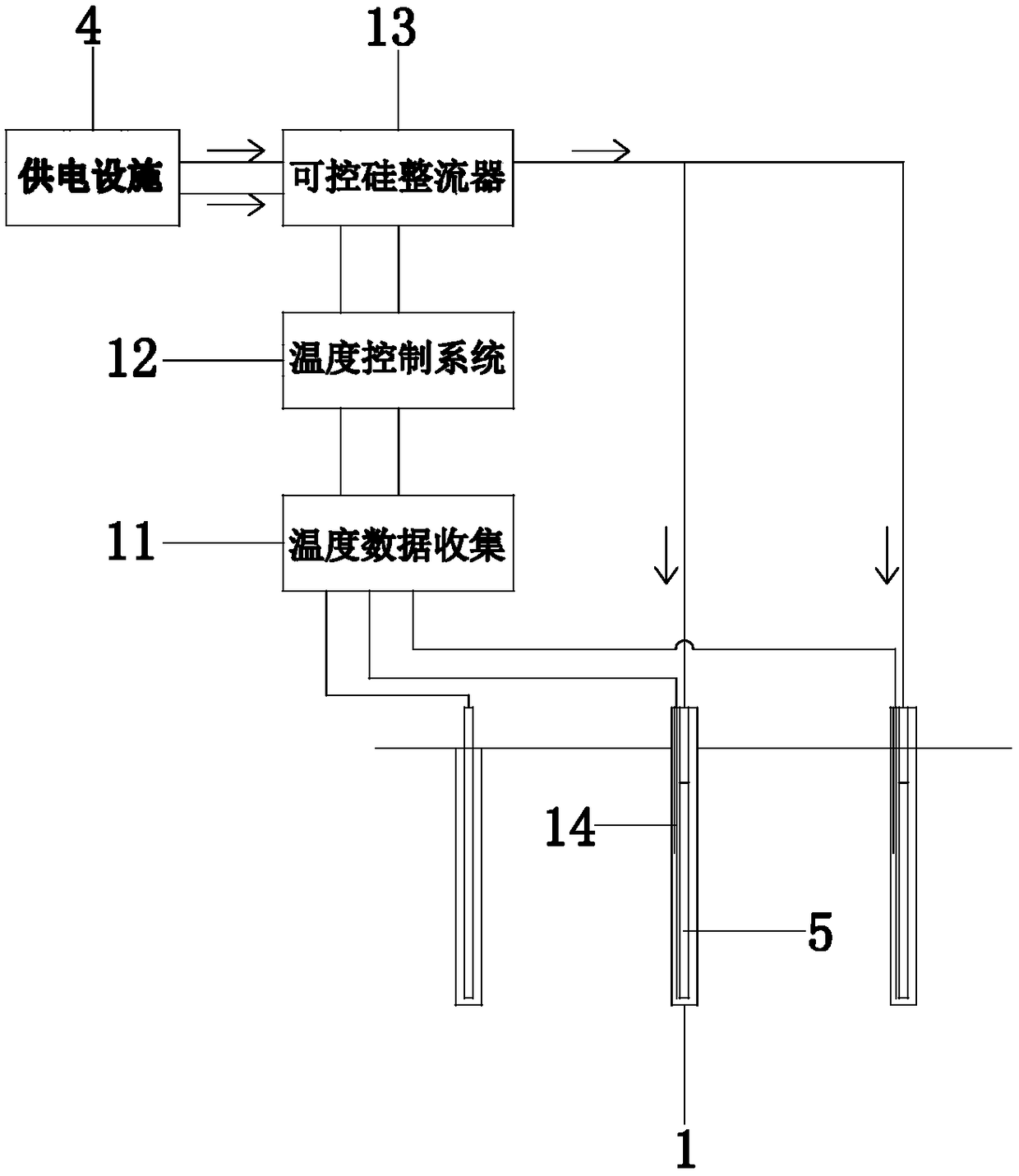
[0033] d. The power supply facility 4 is electrically connected to several heating wells 1 and extraction wells 2, the heating pipe 5 in the heating well 1 is used to heat the polluted site, and the vacuum pump in the extraction well is used to pump out the gaseous pollutants and pollution generated in the pol...


PUM


Abstract

The invention provides an in-situ electric heating desorption restoration technology and device for a contaminated site, belongs to the technical field of soil restoration, and solves the problems that soil and underground water are polluted due to industrial pollution and agricultural chemistry, and the like. The in-situ electric heating desorption restoration technology for the contaminated site comprises the steps of a, inserting a plurality of heating wells and extraction wells into the contaminated site; b, paving a thermal insulating layer on the surface of the contaminated site; c, carrying out precipitation treatment on the underground water of the contaminated site; d, heating the contaminated site through heating pipes in the heating wells, and extracting gaseous pollutants generated by the heated contaminated site and polluted underground water through vacuum pumps in the extraction wells, so as to restore the contaminated site; and e, feeding the gaseous pollutants and the polluted underground water extracted in the step d into a border thermal cycle pipe buried in a stratum at the border for secondary heat exchange, and then feeding the gaseous pollutants and the polluted underground water subjected to secondary heat exchange into a ground extraction treatment device for treatment. The in-situ electric heating desorption restoration technology has the advantages that full automatic temperature control is achieved, waste heat is fully reused, the layout is flexible, a higher scientific and technological level is reached, and the like.

Description

technical field [0001] The invention belongs to the technical field of soil remediation, in particular to an in-situ electric heating desorption repair technology and a device thereof for polluted sites. Background technique [0002] Due to the aggravation of industrial pollution and the wide application of agricultural chemicals, organic pollution of site soil and groundwater is becoming more and more serious. Typical organic pollutants in soil and groundwater include benzene series, organic halides, petroleum hydrocarbons, pesticides, and PCBs. The existence of these pollutants in the soil and groundwater environment may have serious adverse effects on the nearby human body and the surrounding environment. Therefore, reasonable technical means must be used to restore these polluted soil and groundwater, so as to effectively control the human health and ecological environment risk. [0003] As an important technology for remediation of soil and groundwater in highly diffi...

Claims


Application Information

Patent Timeline
Patent Type & Authority Patents(China)
IPC IPC(8): B09C1/06
CPCB09C1/002B09C1/005B09C1/007B09C1/06B09C2101/00
Inventor 张峰刘昊王健华马烈张芝兰顾心爱阮关心
Owner SHANGHAI GREENMENT ENVIRONMENTAL TECH CO L
Why Eureka
Try Eureka