Immersion nozzle for continuous casting

a technology of continuous casting and immersion nozzle, which is applied in the direction of casting apparatus, melt-holding vessels, manufacturing tools, etc., can solve the problems of lowering the quality of steel, unstable flow velocity distribution, and lowering the flow velocity of molten steel in the mold

Active Publication Date: 2009-10-01
KROSAKI HARIMA CORP
View PDF3 Cites 5 Cited by
  • Summary
  • Abstract
  • Description
  • Claims
  • Application Information

AI Technical Summary

Problems solved by technology

Increasing the outlet dimensions results in imbalances in flow velocity distribution between the exit-streams discharged out of the lower portions and the exit-streams out of the upper portions of the outlets, and between the exit-stream out of the right outlet and the exit-stream out of the left outlet.
The imbalanced flows (drifts) impinge on the narrow sidewalls of the mold and then induce unstable patterns of molten steel flow in the mold.
As a result, the level fluctuation at the molten steel surface is caused by excessive reverse flows, and the steel quality is lowered due to entrapment of mold power, and also problems such as breakout occur.
Further, the immersion nozzle of International publication No. 2005 / 049249, which has four or more outlets, not only requires a complicated manufacturing process, but is liable to induce imbalance between the right- and left-hand exit-streams when clogging or thermal wear of the outlets occurs.

Method used


Image

  • Immersion nozzle for continuous casting
  • Immersion nozzle for continuous casting
  • Immersion nozzle for continuous casting

Examples


Embodiment Construction

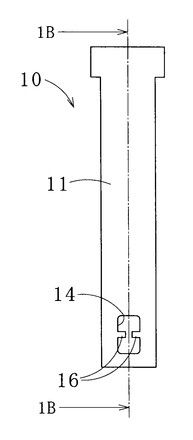
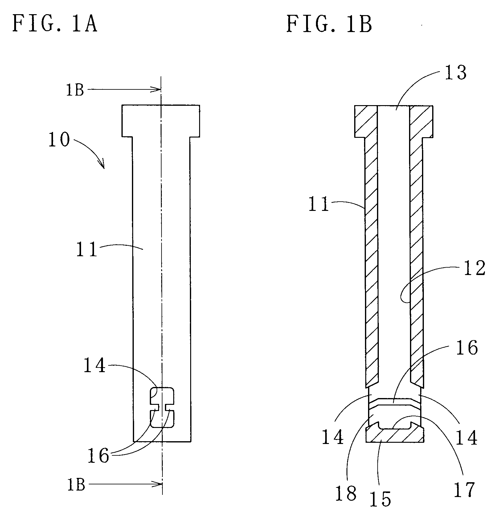
[0050]FIG. 1A shows an immersion nozzle for continuous casting (hereafter, also referred to as “immersion nozzle”) 10 according to one embodiment of the present invention. Throughout the embodiment, the directions are set with the immersion nozzle 10 arranged upright.

[0051]The immersion nozzle 10 includes a cylindrical tubular body 11 with a bottom 15, and a pair of opposing outlets 14, 14. The tubular body 11 has an inlet 13 for entry of molten steel at the upper end of a passage 12 extending inside the tubular body 11. The pair of opposing outlets 14, 14 are disposed at a lower section thereof so as to communicate with the passage 12. The tubular body 11 is made of a refractory material such as alumina-graphite since the immersion nozzle 10 is required to have spalling resistance and corrosion resistance.

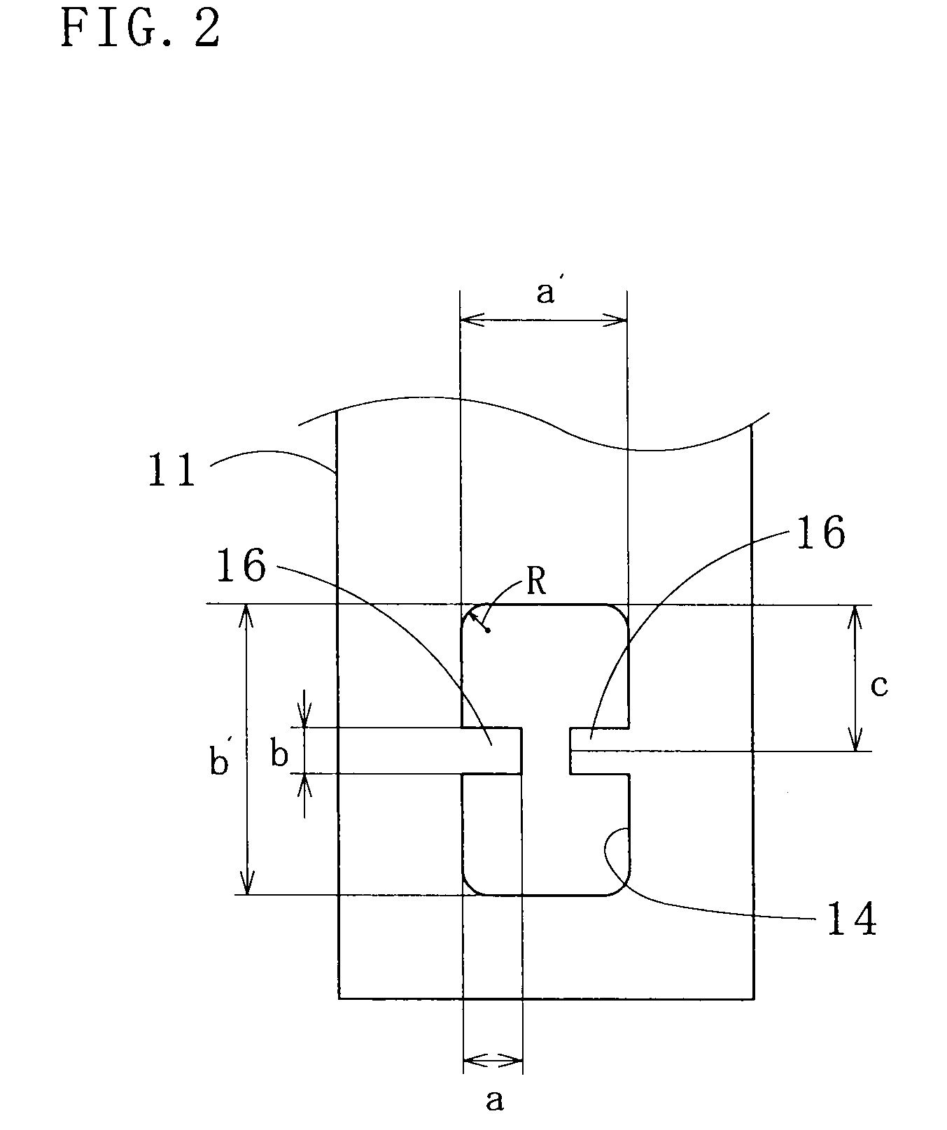
[0052]The outlets 14, 14 have a rectangular configuration with rounded corners, when seen in a front view. The tubular body 11 has opposing ridges 16, 16 that project in the horiz...


PUM

PropertyMeasurementUnit
tilt angleaaaaaaaaaa
velocitiesaaaaaaaaaa
lengthaaaaaaaaaa

Abstract

An immersion nozzle for continuous casting, including (1) a tubular body with a bottom, the tubular body having an inlet for entry of molten steel disposed at an upper end and a passage extending inside the tubular body downward from the inlet, and (2) a pair of opposing outlets disposed in a sidewall at a lower section of the tubular body so as to communicate with the passage, the nozzle comprising: a pair of opposing ridges horizontally projecting into the passage from an inner wall between the pair of outlets, the inner wall defining the passage.

Description

CROSS REFERENCES TO RELATED APPLICATIONS[0001]This application is based upon and claims benefit of priority of Japanese Patent Applications No. 2008-084166 filed on Mar. 27, 2008 and No. 2008-335527 filed on Dec. 27, 2008, the contents of which are incorporated herein by reference.BACKGROUND OF THE INVENTION[0002]1. Field of the Invention[0003]The present invention relates to a continuous casting immersion nozzle for pouring molten steel from a tundish into a mold.[0004]2. Description of the Related Art[0005]In a continuous casting process for producing casting steel products of a predetermined shape by continuously cooling and solidifying molten steel, molten steel is poured into a mold through a continuous casting immersion nozzle (hereafter, also referred to as the “immersion nozzle”) positioned at the bottom of a tundish. Generally, the immersion nozzle includes a tubular body with a bottom, and a pair of outlets. The tubular body has an inlet for entry of molten steel disposed ...

Claims


Application Information

Patent Timeline
Patent Type & Authority Applications(United States)
IPC IPC(8): B22D11/10
CPCB22D41/50
Inventor KIDO, KOJIKURISU, JOJIOTSUKA, HIROSHIMIZOBE, ARITOKURODA, TAKAHIRO
Owner KROSAKI HARIMA CORP
Why Eureka
Try Eureka