
Heat transfer fluid containing nano-additive

a technology of nano-additive and heat transfer fluid, which is applied in the direction of heat-exchange elements, chemistry apparatuses and processes, etc., can solve the problems of reducing the effectiveness of nano-additive particles in enhancing the thermal conductivity of nano-additive particles do not disperse well in the heat transfer fluid, and the heat transfer efficiency of non-aqueous heat transfer fluids is lower than water-based fluids

Inactive Publication Date: 2015-04-14
ADVANCED FLUID TECH INC
View PDF8 Cites 2 Cited by
  • Summary
  • Abstract
  • Description
  • Claims
  • Application Information

AI Technical Summary

Benefits of technology

The heat transfer fluid achieves a 10-20% increase in thermal conductivity and maintains low moisture levels, reducing maintenance costs and preventing issues like ice formation, while maintaining fluid stability and efficiency.

Problems solved by technology

Non-aqueous heat transfer fluids are normally used in extremely low or high temperature applications where water-based heat transfer fluids cannot operate due to freezing or boiling problems.
Non-aqueous heat transfer fluids have lower heat transfer efficiency compared to water-based fluids because the non-aqueous heat transfer fluids have lower specific heat and thermal conductivity compared to the water-based heat transfer fluids.
However, the nano-additive particles do not disperse well in the heat transfer fluid due to their significant density difference with the carrier fluid.
When surfactants are used to disperse nano-additive particles in the heat transfer fluid, the surface of the nano-additive particles gets covered with the surfactant and diminishes the effectiveness of the nano-additive particles for enhancing the thermal conductivity of the heat transfer fluid.
Another common problem associated with non-aqueous heat transfer fluids is the presence of moisture in the heat transfer fluid.
In low temperature applications, the moisture can freeze and form ice crystals in the heat transfer fluid and cause problems in the re-circulating heat transfer fluid loop.
Moisture can also result in degradation of the heat transfer fluid.

Method used


Image

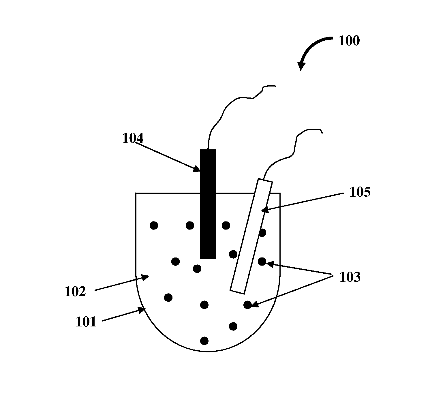
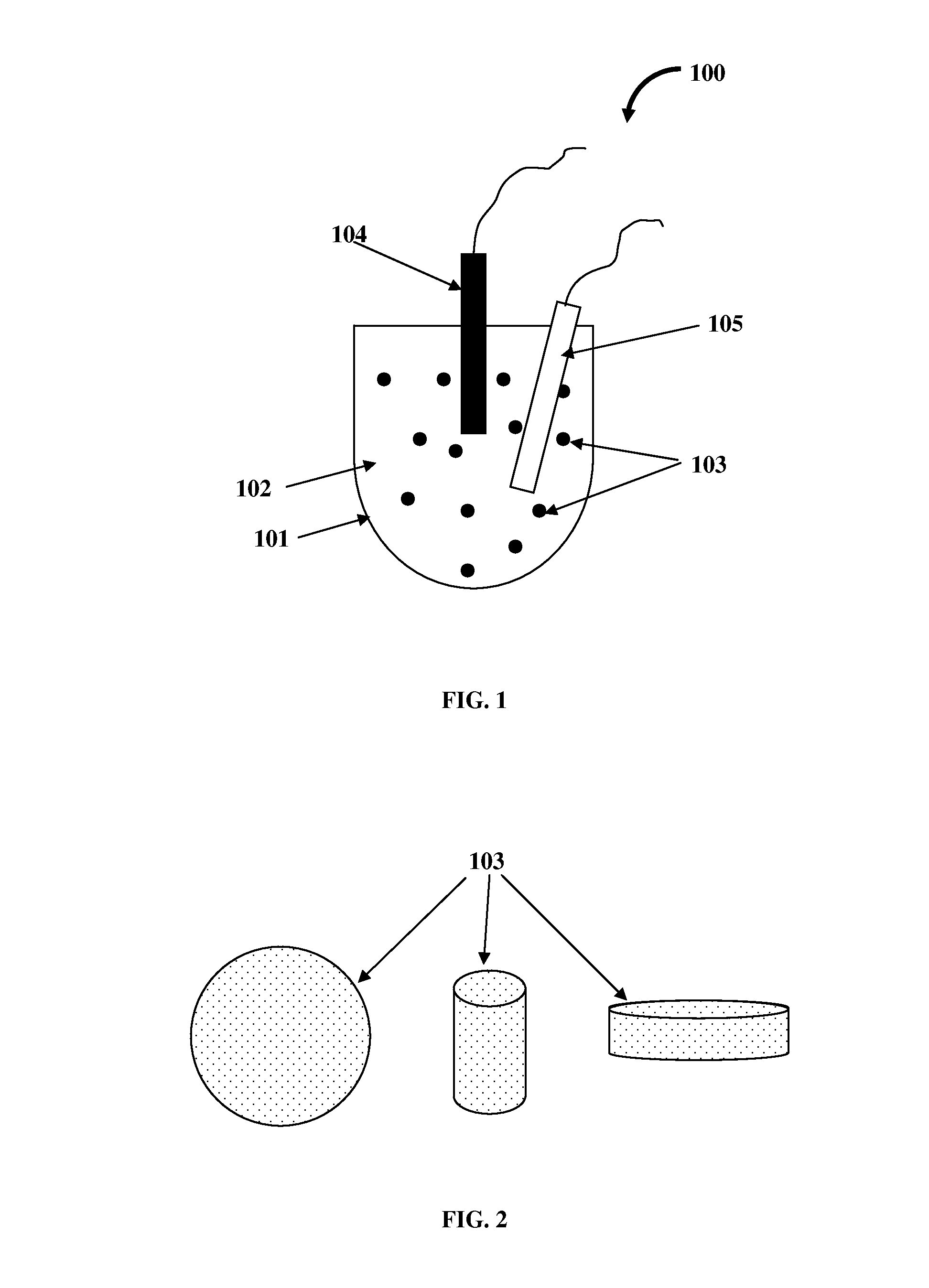
  • Heat transfer fluid containing nano-additive
  • Heat transfer fluid containing nano-additive

Examples


example 1

[0045]A heat transfer fluid composition was prepared using the following steps:[0046](1) 500 ml of commercially available hydrocarbon based HTF, Dynalene MV (Dynalene Inc.), was obtained and placed in a glass beaker. The glass beaker was placed in an ice bath. A sample of the fluid was removed and tested for moisture content and thermal conductivity.[0047](2) 0.42 g of porous carbon nano-particles (from Y-Carbon, King Of Prussia, Pa.) of an average diameter 20 nm was added to the hydrocarbon fluid.[0048](3) A homogenizer and a wand type sonicator were placed in the fluid.[0049](4) Homogenization and sonication were carried out simultaneously for about 10 minutes.[0050](5) A sample of the heat transfer fluid was removed and tested for the nano-additive particle / agglomerate size distribution. An average size of 120 nm was obtained.[0051](6) A sample of the heat transfer fluid was also tested for moisture content and thermal conductivity.[0052](7) The moisture content of the heat trans...

example 2

[0053]A heat transfer fluid composition was prepared using the following steps:[0054](1) 700 ml of commercially available silicone based HTF, Syltherm XLT (Dow Chemicals, Midland, Mich.), was obtained and placed in a glass beaker. The glass beaker was placed in an ice bath. A sample of the fluid was removed and tested for moisture content and thermal conductivity.[0055](2) 6.0 g of 13X molecular sieve (purchased from Aldrich Chemicals) was ground to 100 nm particles using a micronizer device. The resultant particles were added to the silicone fluid in the beaker.[0056](3) A homogenizer and a wand type sonicator were placed in the fluid.[0057](4) Homogenization and sonication were carried out simultaneously for about 30 minutes.[0058](5) A sample of the heat transfer fluid was removed and tested for the particle / agglomerate size distribution. An average size of 200 nm was obtained.[0059](6) The sample of the heat transfer fluid was also tested for moisture content and thermal conduct...

example 3

[0061]A heat transfer fluid composition was prepared using the following steps:[0062](1) 500 ml of commercially available hydrocarbon based HTF, Dynalene HF-LO (Dynalene, Inc., Whitehall, Pa.), was obtained and placed in a glass beaker. The glass beaker was placed in an ice bath. A sample of the fluid was removed and tested for moisture content and thermal conductivity.[0063](2) 20 g of porous and fibrous carbon material (from Y-Carbon, Inc., King Of Prussia, Pa.) of average diameter 10 nm and length 1 micron (aspect ratio of 1:100) was added to the hydrocarbon carrier fluid.[0064](3) A homogenizer and a sonicator (wand type) were placed in the fluid.[0065](4) Homogenization and sonication were carried out simultaneously for about 1 hour.[0066](5) A sample of the heat transfer fluid was removed and tested for the particle / agglomerate size distribution. An average size of 500 nm was obtained.[0067](6) The sample of the heat transfer fluid was also tested for moisture content and ther...


PUM

PropertyMeasurementUnit
diameteraaaaaaaaaa
porosityaaaaaaaaaa
densityaaaaaaaaaa

Abstract

A heat transfer fluid comprising a carrier fluid and a nano-additive is provided. The heat transfer fluid is manufactured by dispersing the nano-additive in the carrier fluid. The nano-additive comprises nano-particles having a porous structure that provides dispersion stability of the nano-additive in the heat transfer fluid. The nano-additive structure has an aspect ratio of about 1.0 to about 10,000, a porosity of about 40% to about 85%, a density of about 0.4 g / cc to about 3.0 g / cc, an average pore diameter of about 0.1 nanometer to about 100 nanometers, and a specific surface area of about 1 m2 / g to about 4000 m2 / g. The nano-additive increases the heat transfer efficiency of the heat transfer fluid and also reduces the moisture content of the heat transfer fluid.

Description

CROSS REFERENCE TO RELATED APPLICATIONS[0001]This application claims the benefit of provisional patent application No. 61 / 296,030 titled “Heat Transfer Fluid Containing Nano-additive”, filed on Jan. 19, 2010 in the United States Patent and Trademark Office.[0002]The specification of the above referenced patent application is incorporated herein by reference in its entirety.FIELD OF THE INVENTION[0003]This invention, in general, relates to heat transfer fluids containing a nano-additive, and more particularly, this invention relates to increasing the heat transfer efficiency and reducing the moisture content of a non-aqueous heat transfer fluid using a nano-additive.BACKGROUND[0004]Heat transfer fluids are used in a variety of applications including reactor cooling / heating, plastic molding, constant temperature baths, automotive coolant systems, cold storage, climactic chambers, heating, air-conditioning, etc. The primary objective of a heat transfer fluid is to remove heat from the ...

Claims


Application Information

Patent Timeline
Patent Type & Authority Patents(United States)
IPC IPC(8): C09K5/10
CPCC09K5/10
Inventor MOHAPATRA, SATISH CHANDRA
Owner ADVANCED FLUID TECH INC
Learn More