
Power generation system using an alkaline fuel cell and fuel gas for alkaline fuel cells used in the system

a technology of power generation system and fuel gas, which is applied in the direction of fuel cell details, electrochemical generators, aqueous electrolyte fuel cells, etc., can solve the problems of not being able to use expensive noble metal catalysts and their actual output is not as high as expected even when using hydrogen gas, so as to improve ion conductivity, increase hydroxy-ion concentration, and increase output

Inactive Publication Date: 2015-03-10
TOKUYAMA CORP
View PDF11 Cites 0 Cited by
  • Summary
  • Abstract
  • Description
  • Claims
  • Application Information

AI Technical Summary

Benefits of technology

The present invention is about improving the output of alkaline fuel cells. By using hydrogen gas containing a basic compound as a fuel, higher output can be obtained compared to conventional fuel cells using hydrogen gas. This is because the system includes an electrode catalyst and anion conductive ionomer, which can hydrate the basic compound and absorb water. This increases the concentration of hydroxy-ions and enhances ion conductivity, lowering the ohm loss and anode reaction overvoltage. Overall, this invention is useful for practical use of alkaline fuel cells.

Problems solved by technology

In the solid-polymer type fuel cell wherein the cation-exchange membrane is used for a solid electrolyte membrane, only an expensive noble metal catalyst is usable as the catalyst in the electrode due to the strongly acidic reaction field.
However, while the alkaline fuel cell using an anion-exchange membrane as an electrolyte membrane has various advantages over those using a cation-exchange membrane as mentioned above, its actual output is not as high as expected even when using the hydrogen gas.

Method used


Image

  • Power generation system using an alkaline fuel cell and fuel gas for alkaline fuel cells used in the system
  • Power generation system using an alkaline fuel cell and fuel gas for alkaline fuel cells used in the system

Examples


examples

[0068]Hereinafter, the present invention will be explained further in detail by using examples, but the present invention is not limited to these examples. Note that operating characteristics of fuel cells in Examples and Comparative Examples are as follows.

[0069]1) Measurements of Concentration of Basic Compound in Hydrogen Gas Fuel

[0070]Hydrogen gas containing a basic compound was passed through 100 ml of 10 mM-sulfuric acid aqueous solution (absorbing liquid), which was continued until the volume of the passing hydrogen gas became 1 L (at 25° C.). The concentration of the basic compound in the absorbing liquid was separated and analyzed by ion chromatography. The concentration of the basic compound was calculated by using the following formula and the peak area of chromatographic peak obtained when measuring the known concentration (in mol / L) of the basic compound aqueous solution (so-called standard concentration solution).

Amount of the basic compound in the absorbing liquid (mo...

examples 1 to 9

[0095]Hydrogen gases containing a variety of concentrations of the basic compound were supplied to the anode for performing the output test. For the oxidizing agent gas, air containing 380 ppm of carbon dioxide was used. The results are shown in Table 1. Also, the concentration of the included basic compound to the hydrogen was measured. The results are also shown in Table 1.

examples 10 to 15

[0098]Except for using air containing no carbon dioxide as the oxidizing agent gas, output test was performed as in Example 1. The results are shown in Table 2.


PUM

PropertyMeasurementUnit
operating temperatureaaaaaaaaaa
pKaaaaaaaaaaa
temperaturesaaaaaaaaaa

Abstract

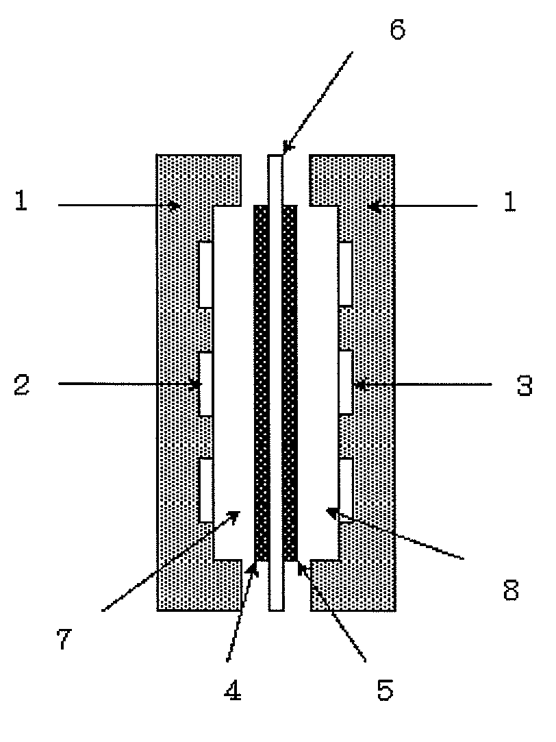
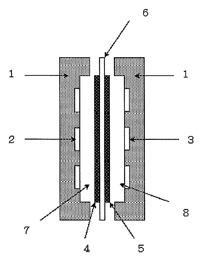
A power generation system includes an alkaline fuel cell provided with an electrolyte membrane which is an anion exchange membrane and a pair of electrodes (an anode and a cathode) arranged on the both sides of the electrolyte membrane. The alkaline fuel cell can generate an electric power by supplying a fuel gas and an oxidizing agent gas to the anode side and the cathode side, respectively. The power generation system uses a hydrogen gas containing a basic compound such as ammonia as the fuel gas to be supplied to the anode side.

Description

[0001]This application is a U.S. national stage application of PCT / JP2010 / 062304 filed on Jul. 22, 2010 which claims priority of Japanese patent document 2009-177642 filed on Jul. 30, 2009, the entirety of which is incorporated herein by reference.TECHNICAL FIELD[0002]The present invention relates to a power generation system using an alkaline fuel cell using an electrolyte membrane which is an anion-exchange membrane, and fuel gas used therein.BACKGROUND OF THE INVENTION[0003]A fuel cell is a power generation system to generate electrical power from chemical energy. This is classified in several types based on the operation mechanisms and materials to be used, such as alkaline-type fuel cell, phosphoric-acid fuel cell, molten carbonate fuel cell, solid-electrolyte fuel cell and solid-polymer type fuel cell, and various forms of fuel cells have been proposed and examined. Among these, the alkaline fuel cell and solid-polymer type fuel cell are expected to use as medium to small-size...

Claims


Application Information

Patent Timeline
Patent Type & Authority Patents(United States)
IPC IPC(8): H01M8/22H01M8/08
CPCH01M8/083H01M8/222Y02E60/50H01M8/06H01M8/10H01M8/02
Inventor WATANABE, SHINFUKUTA, KENJIYANAGI, HIROYUKI
Owner TOKUYAMA CORP
Learn More