
High SMSR unidirectional etched lasers and low back-reflection photonic device

a back-reflection photonic device and laser technology, applied in semiconductor lasers, instruments, optical elements, etc., can solve the problems of reducing the spectral purity of the laser, generating optical radiation in different wavelengths, and unidirectional behavior of the ring laser, so as to improve the side-mode suppression ratio (smsr), prevent back-reflection, and enhance the unidirectionality of the semiconductor laser

Active Publication Date: 2014-11-18
MACOM TECH SOLUTIONS HLDG INC
View PDF7 Cites 1 Cited by
  • Summary
  • Abstract
  • Description
  • Claims
  • Application Information

AI Technical Summary

Benefits of technology

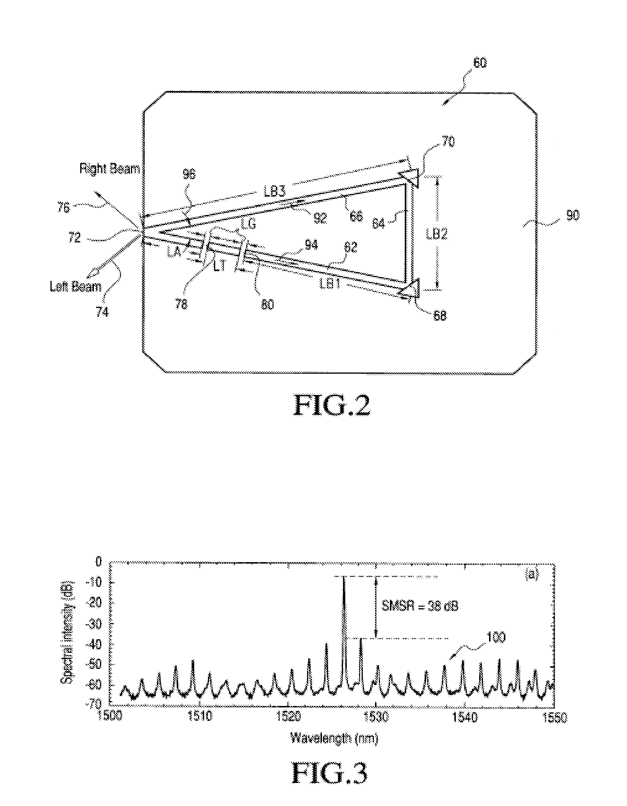
The present invention provides a novel technique for achieving unidirectionality in semiconductor photonic devices such as ring lasers and V-shaped lasers. This is achieved by positioning etched gaps in the lasers with respect to the output facet or the length of the legs in a V-shaped laser. The invention also enhances the side-mode suppression ratio (SMSR) by forming at least one air gap in the laser cavity. Additionally, the invention minimizes back-reflection by using a facet at the Brewster angle on the output end of the photonic device.

Problems solved by technology

In addition, unidirectional behavior in ring lasers also has been described in the prior art.
A laser source has a large number of possible longitudinal modes, and although it has the tendency to operate in the one longitudinal mode that leads to the maximum gain, some other modes are also partially amplified, causing it to generate optical radiation in different wavelengths and reducing its spectral purity.
However, due to the inherent difficulty in building accurately positioned cleaved facets and the tolerances involved in placing two cleaved cavities in close proximity to each other to form a gap, large-scale manufacture of these lasers did not materialize.
However, these etched facets where not equivalent in reflectivity to cleaved facets and the etched versions of these devices were less efficient than their cleaved counterparts.

Method used


Image

  • High SMSR unidirectional etched lasers and low back-reflection photonic device
  • High SMSR unidirectional etched lasers and low back-reflection photonic device
  • High SMSR unidirectional etched lasers and low back-reflection photonic device

Examples


Embodiment Construction

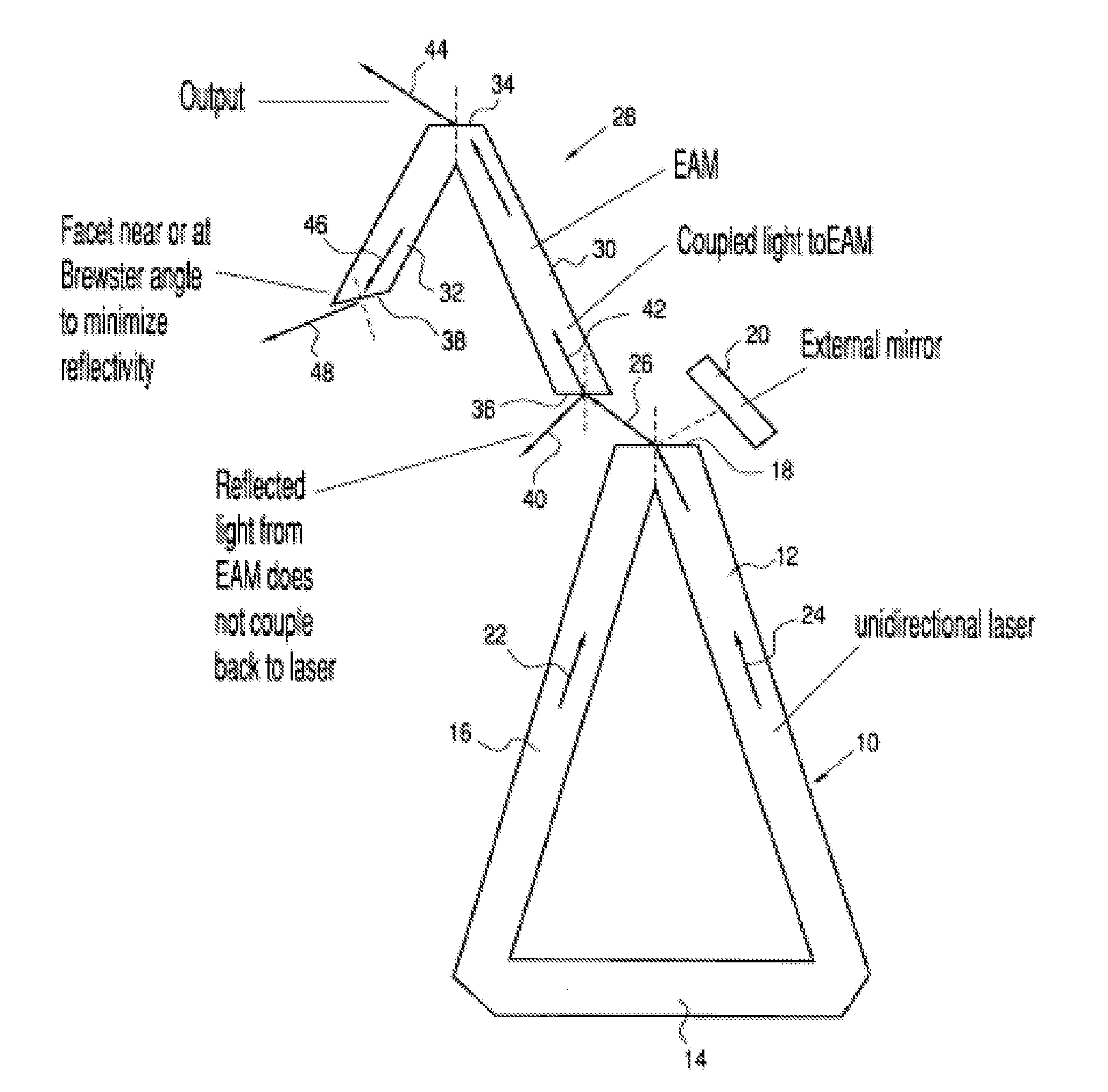
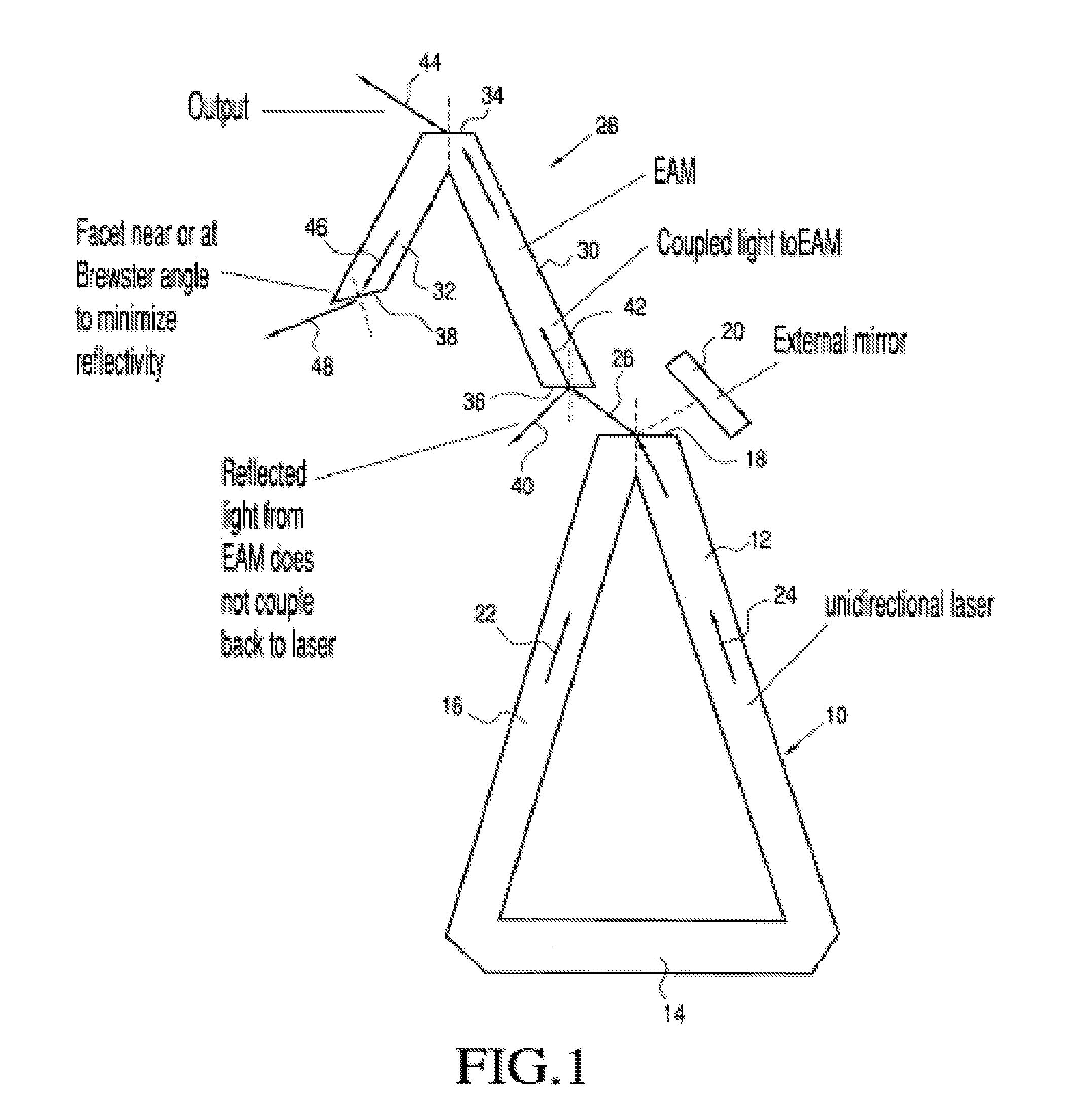
[0018]FIG. 1 illustrates a photonic device in the form of a monolithic, unidirectional, triangular ring laser cavity 10 having legs 12, 14, and 16, with legs 12 and 16 joining at an exit facet 18. Unidirectionality is obtained in laser 10 by the provision of an external mirror 20, which reflects the clockwise light 22 propagating in the laser and emitted at exit facet 18 back into the laser to reinforce the counterclockwise light 24. A portion of the light 24 is emitted at facet 18 as beam 26, which is coupled into another photonic device 28 such as a semiconductor optical amplifier (SOA), an electroabsorption modulator (EAM), or the like. In the illustrated arrangement, the device 28 is a V-shaped EAM which includes first and second legs 30 and 32 joined at respective first ends at an output facet 34, with the second end of leg 30 having an inlet facet 36 positioned to receive emitted beam 26, and the second end of leg 32 terminating at its extreme, or distal, end at a facet 38, wh...


PUM

PropertyMeasurementUnit
angleaaaaaaaaaa
angle of incidenceaaaaaaaaaa
lengthaaaaaaaaaa

Abstract

Unidirectionality of lasers is enhanced by forming one or more etched gaps (78, 80) in the laser cavity. The gaps may be provided in any segment of a laser, such as any leg of a ring laser, or in one leg (62) of a V-shaped laser (60). A Brewster angle facet at the distal end of a photonic device coupled to the laser reduces back-reflection into the laser cavity. A distributed Bragg reflector is used at the output of a laser to enhance the side-mode suppression ratio of the laser.

Description

CROSS REFERENCE TO RELATED APPLICATIONS[0001]This application is a Divisional under 35 U.S.C. 120 of copending U.S. application Ser. No. 10 / 802,734, filed Mar. 18, 2004, now U.S. Pat. No. 7,817,702, which claims the benefit, under 35 U.S.C. 119(e) of U.S. Provisional Application No. 60 / 455,562, filed Mar. 19, 2003, the disclosure of which is hereby incorporated herein by reference.FIELD OF THE INVENTION[0002]The present invention relates, in general, to a method and apparatus for providing unidirectional emission from an etched laser cavity and for providing low back-reflection from photonic devices, and in particular to photonic devices coupled to the laser output. More particularly, the invention relates to V-shaped lasers and triangular ring lasers with etched gaps to control the unidirectionality of emissions at the outputs of the lasers by providing high side-mode suppression and to the use of an etched facet at or near a Brewster angle to minimize back-reflection in a photonic...

Claims


Application Information

Patent Timeline
Patent Type & Authority Patents(United States)
IPC IPC(8): H01S3/083H01S5/14G02B6/12H01S5/065H01S3/00G02F1/17H01S3/08H01S5/10H01S5/00H01S5/125
CPCG02B6/12004H01S5/0085H01S5/125H01S5/1082H01S5/1021H01S5/1071H01S5/005H01S5/0656H01S5/14H01S5/0287H01S5/0687H01S5/1085H01S5/06817
Inventor BEHFAR, ALEX A.SCHREMER, JR., ALFRED T.STAGARESCU, CRISTIAN B.
Owner MACOM TECH SOLUTIONS HLDG INC
Learn More