
Method and device for magnetic domain refinement of oriented electrical steel plate

a technology of oriented electrical steel plate and magnetic domain, which is applied in the field of method and device for miniaturizing the magnetic domain of a directional electric steel plate, can solve the problems of low production efficiency, high manufacturing cost, and difficulty in controlling the depth and width of groove formation, so as to reduce the deviation of the depth of the groove, improve the quality of the groove, and secure the effect of iron loss improvement ra

Active Publication Date: 2019-03-07
POHANG IRON & STEEL CO LTD
View PDF12 Cites 1 Cited by
  • Summary
  • Abstract
  • Description
  • Claims
  • Application Information

AI Technical Summary

Benefits of technology

The present invention provides a method for improving the magnetic domain miniaturizing efficiency and workability of an electrical steel plate by using a laser. This method can secure higher iron loss improvement rates and minimize deterioration of magnetic flux density. Additionally, this method can prevent damage to equipment caused by back reflection and enhance the quality of products by more efficiently removing contaminants.

Problems solved by technology

The temporal magnetic domain miniaturization method has a disadvantage of losing the magnetic domain miniaturization effect after the stress removing and annealing.
However, such a method causes damage to an insulating coating layer on the surface of the steel plate and thus, recoating is required, and there is a disadvantage that the manufacturing cost is high because the magnetic domain miniaturization is performed in an intermediate process rather than a final product
In the case of the etching method, it is difficult to control groove formation depth and width, and it is difficult to guarantee the iron loss property of the final product, and it is disadvantageous in that the etching method is not eco-friendly because an acid solution is used.
In the case of the method using the roll, there is a disadvantage that the stability, reliability, and process are complicated for mechanical processing.

Method used

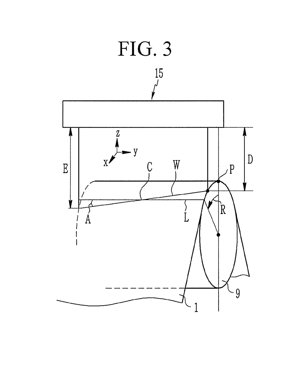

Image

  • Method and device for magnetic domain refinement of oriented electrical steel plate
  • Method and device for magnetic domain refinement of oriented electrical steel plate
  • Method and device for magnetic domain refinement of oriented electrical steel plate

Examples


Embodiment Construction

[0074]The terms used below is for the purpose of describing specific exemplary embodiments only and are not intended to be limiting of the present invention. The singular forms used herein include plural forms as well, if the phrases do not clearly have the opposite meaning. “including” used in the specification means that a specific feature, region, integer, step, operation, element and / or component is embodied and other specific features, regions, integers, steps, operations, elements, components, and / or groups are not excluded.

[0075]Hereinafter, exemplary embodiments of the present invention will be described so as to be easily implemented by those skilled in the art, with reference to the accompanying drawings. As those skilled in the art would realize, the described embodiments may be modified in various different ways, all without departing from the spirit or scope of the present invention. Therefore, the present invention can be implemented in various different forms, and is ...


PUM

PropertyMeasurementUnit
angleaaaaaaaaaa
depthaaaaaaaaaa
depthaaaaaaaaaa

Abstract

By optimizing equipment and processing, magnetic domain miniaturization efficiency can be increased, workability can be improved, and processing ability can be increased through same. Provided is a method for miniaturizing the magnetic domains of a directional electric steel plate, the method comprising: a steel plate supporting roll position adjusting step of controlling the vertical direction position of a steel plate while supporting the steel plate progressing along a production line; and a laser emitting step of melting the steel plate by emitting a laser beam to form grooves on the surface of the steel plate, wherein the laser emitting step includes an angle changing step of changing an emitting line angle of the laser beam with respect to a width direction of the steel plate while an optical system emitting the laser beam onto the steel plate is rotated with respect to the steel plate, and a focal distance maintaining step of changing a tilt of the steel plate supporting roll which supports the steel plate according to a change in focal distance of the laser beam in the width direction of the steel plate.

Description

TECHNICAL FIELD[0001]The present invention relates to a method and a device for miniaturizing magnetic domains of a directional electric steel plate which permanently miniaturizes magnetic domains of a steel plate by emitting a laser to the directional electric steel plate.BACKGROUND ART[0002]For example, a directional electric steel plate with magnetic characteristics such as low iron loss and high magnetic flux density is required in order to reduce power loss and improve efficiency of electric devices such as a transformer.[0003]There is disclosed a technique of miniaturizing magnetic domains in a vertical direction to a rolling direction by a mechanical method or emitting a laser beam to a surface of the steel plate so as to reduce the iron loss of the directional electric steel plate.[0004]The method for miniaturizing the magnetic domains may be broadly divided into temporal magnetic domain miniaturization and permanent magnetic domain miniaturization depending on whether or no...

Claims


Application Information

Patent Timeline
Patent Type & Authority Applications(United States)
IPC IPC(8): B23K26/082B23K26/16B23K26/354B23K26/364B23K26/70B23K37/047
CPCB23K26/082B23K26/16B23K26/354B23K26/364B23K26/704B23K37/047C21D8/1277C21D8/1294C21D10/005C21D9/46C21D1/74C21D9/0012C21D9/561C21D9/562C21D9/563C21D9/564C21D8/1238C21D10/00C21D8/12B23K26/08B23K26/352B23K26/70
Inventor LEE, GYOO TAEKCHUN, MYUNG SIKHONG, SEONG CHEOLMIN, KI YOUNG
Owner POHANG IRON & STEEL CO LTD
Learn More