Method for reducing evaporated fuel emission, canister and adsorbent therefor
a technology of evaporated fuel and canister, which is applied in the direction of machines/engines, combustion air/fuel air treatment, and separation processes, etc., can solve the problems of deteriorating low-emission performance, insufficient adsorption efficiency of evaporated fuel gas, and increasing the environmental measures to be required for motor vehicles. , to achieve the effect of reducing the adsorption rate, and maintaining the adsorption performance required
- Summary
- Abstract
- Description
- Claims
- Application Information
AI Technical Summary
Benefits of technology
Problems solved by technology
Method used
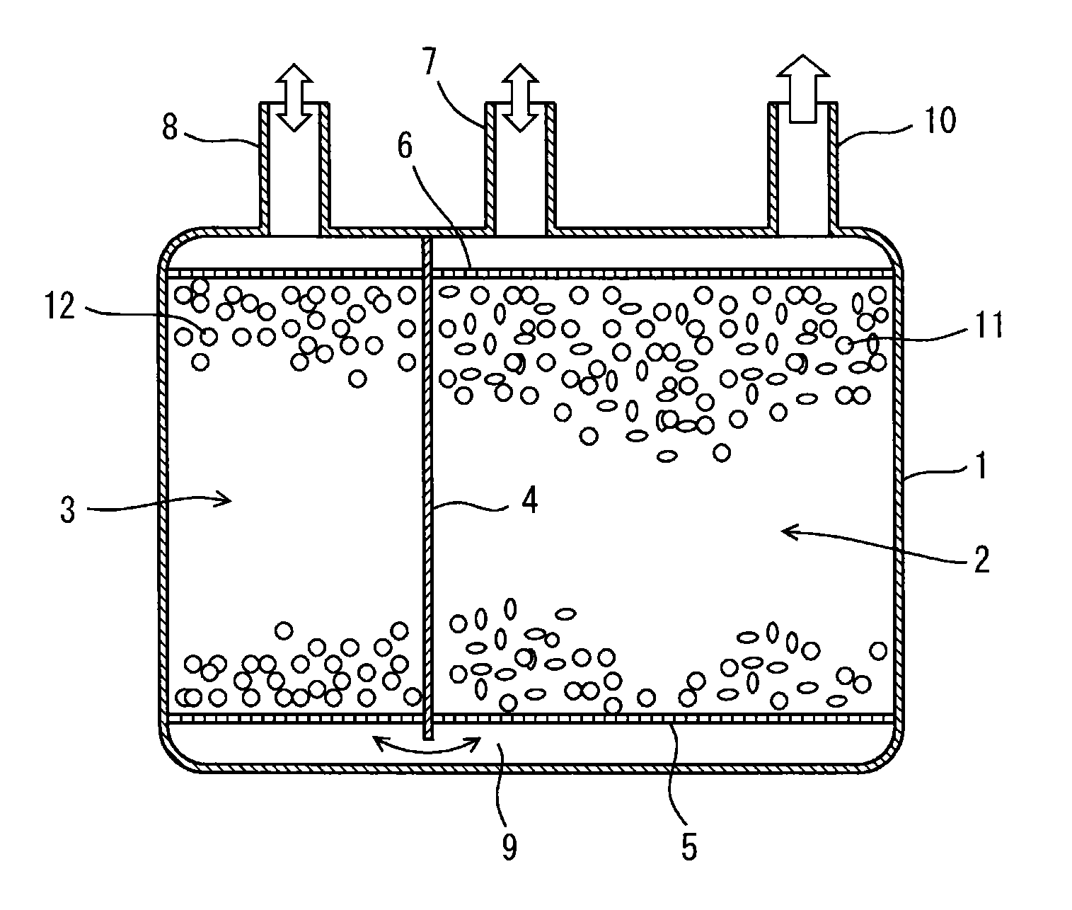
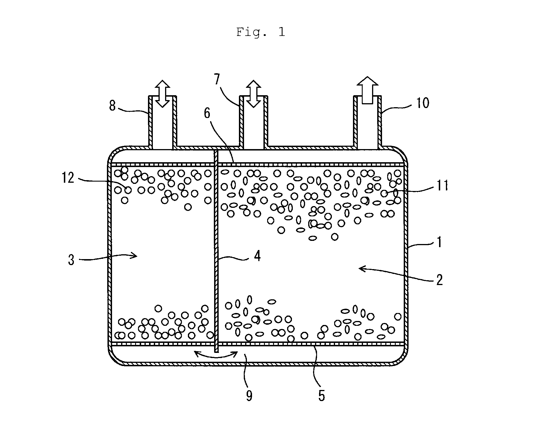
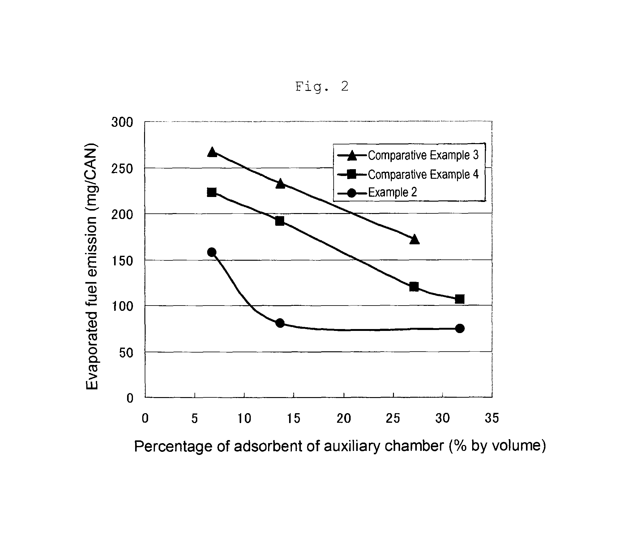
Image

Examples
experimental example 1
Comparative Example 1
[0098]A coal-based activated carbon (manufactured by Kuraray Chemical Co., Ltd., activated carbon “2GK-H”) was used as the first adsorbent and the second adsorbent. For the evaluation of the evaporated fuel emission, the activated carbon was used in a ratio of 1900 ml of the first adsorbent (the above-mentioned “2GK-H”) relative to 300 ml of the second adsorbent (the above-mentioned “2GK-H”).
examples 1 to 3
[0099]A coal-based activated carbon (manufactured by Kuraray Chemical Co., Ltd., activated carbon “2GK-H”) was pulverized by a pulverizer to give a powder having a particle size of not more than 100 μm. In the proportions shown in Table 1 relative to 100 parts by mass of the obtained activated carbon powder (average particle diameter: 25 μm), a solid diluent (average particle diameter: 5 μm), a lubricant [a carboxymethyl cellulose (CMC)], a binder resin (manufactured by Nippon Carbide Industries Co., Inc., an acryl emulsion “Nikasol FX-6074”, solid contents: 50% by mass), and water were mixed with the obtained activated carbon powder. The resulting mixture was extruded by a hydraulic extruder to form a molded product having a diameter of 2 mm, and the molded product was cut into 3 to 5 mm length. The cut product was granulated and sized and dried at 120° C. for 12 hours to give a second adsorbent. The performances of the second adsorbent are shown in Table 1. The first adsorbent (th...
examples 4 and 5
[0100]In the same manner as in Examples 1 to 3, a coal-based activated carbon (manufactured by Kuraray Chemical Co., Ltd., activated carbon “2GK-H”) was pulverized to give an activated carbon powder; and 100 parts by mass of the obtained activated carbon powder (average particle diameter: 25 μm), 100 parts by mass of calcium carbonate (average particle diameter: 0.3 μm), 3.2 parts by mass of a lubricant (CMC), 35 parts by mass of a binder resin (manufactured by Nippon Carbide Industries Co., Inc., an acryl emulsion “Nikasol FX-6074”, solid contents: 50% by mass), and 165 parts by mass of water were mixed.
[0101]The resulting mixture was extruded by a hydraulic extruder to form a molded product having a diameter of 2 mm, and the molded product was cut into 3 to 4 mm length. The cut product was granulated and sized and dried at 120° C. for 2 to 3 hours. The dried granular product was boiled for washing in a 2 mol / L hydrochloric acid in a ratio of 1 L of the hydrochloric acid relative t...
PUM
| Property | Measurement | Unit |
|---|---|---|
| concentration | aaaaa | aaaaa |
| pore size | aaaaa | aaaaa |
| pore size | aaaaa | aaaaa |
Abstract
Description
Claims
Application Information
 - R&D
- Intellectual Property
- Life Sciences
- Materials
- Tech Scout
- Unparalleled Data Quality
- Higher Quality Content
- 60% Fewer Hallucinations
Browse by: Latest US Patents, China's latest patents, Technical Efficacy Thesaurus, Application Domain, Technology Topic, Popular Technical Reports.
© 2025 PatSnap. All rights reserved.Legal|Privacy policy|Modern Slavery Act Transparency Statement|Sitemap|About US| Contact US: help@patsnap.com