Reciprocating devices

a technology of reciprocating devices and combustion engines, applied in the direction of machines/engines, climate sustainability, waterborne vessels, etc., can solve the problems of reduced efficiency, reduced efficiency, and unsatisfactory fact, so as to reduce co2 emissions, improve efficiency, and high power density

Active Publication Date: 2008-06-19
HINDERKS MITJA VICTOR
View PDF24 Cites 144 Cited by
  • Summary
  • Abstract
  • Description
  • Claims
  • Application Information

AI Technical Summary

Benefits of technology

[0007]The inventions comprise commercial long-life reciprocating internal combustion (IC) engines having high power densities, and having absolutely no cooling whatever. They are preferably mounted in an insulated casing. Main objectives are to substantially improve efficiency and to reduce CO2 emissions. In most embodiments, the number of moving parts per cylinder, and the number of cylinders required for a desired output, are greatly reduced. Additional objectives are to improve power-to-weight and power-to-bulk ratios many fold, and to make reciprocating IC engines more silent and vibration-free. In many embodiments, all the principle components are of ceramic material. The inventions further comprise using high-temperature and opti

Problems solved by technology

The expansion drives the piston and consequently engine while the heat product of the cycle is almost wholly unused—in fact considered undesirable since efforts are made to dissipate it as effectively as possible, by means of conduction through cylinder walls and head to general radiation and to the cooling system.
At all other times the engine is running colder and therefore less efficient.
Today, almost all engines during most of their operating life time run at temperatures substantially below the peak temperatures they are designed for, and so at lower efficiency because

Method used


Image

  • Reciprocating devices
  • Reciprocating devices
  • Reciprocating devices

Examples


Embodiment Construction

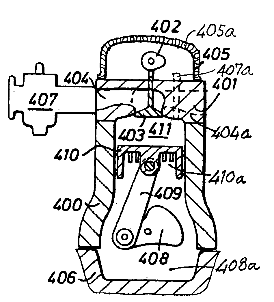
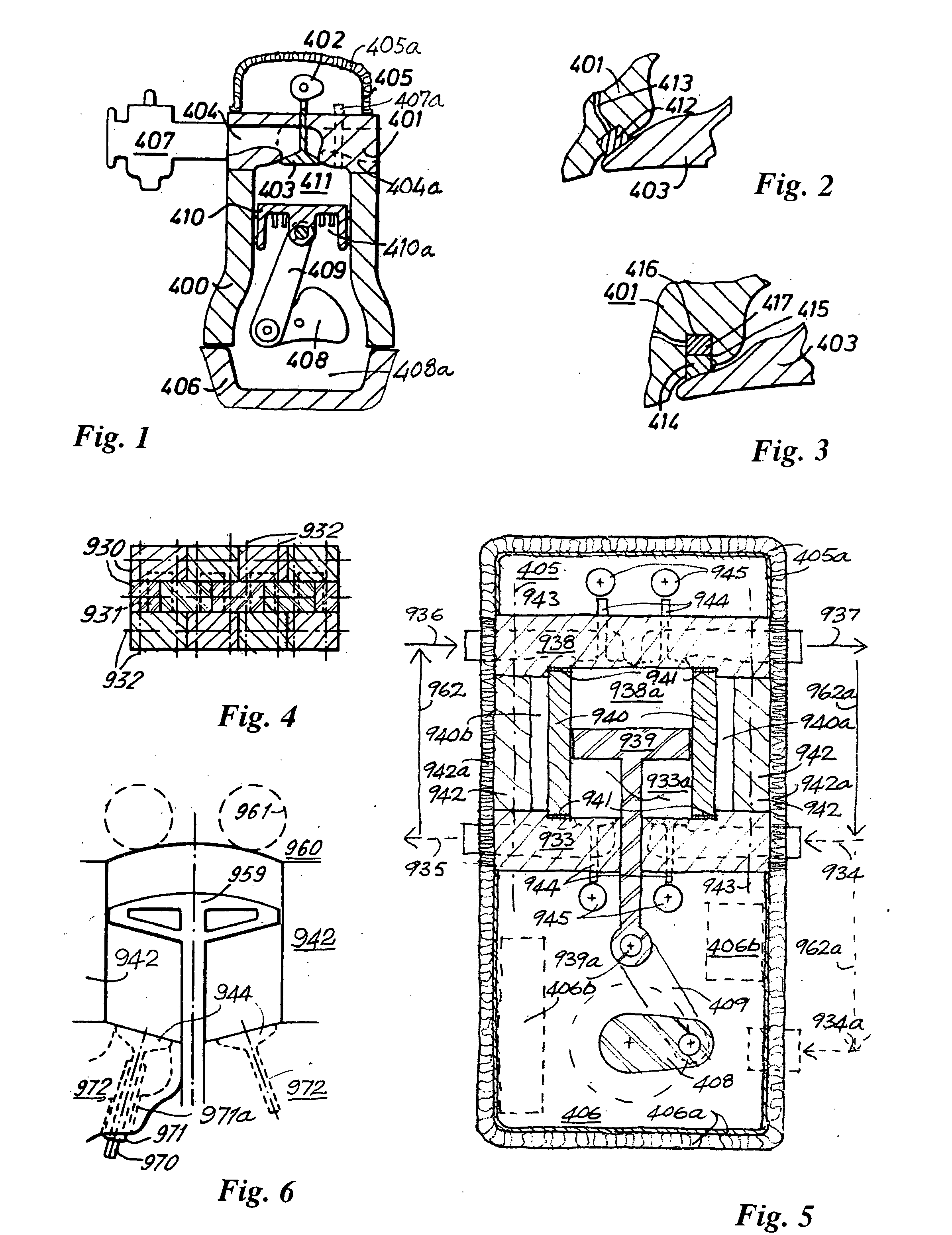
[0159]An important objective of the invention is to provide at engines having greater power-to-weight ratios, power-to-bulk ratios, and substantially greater efficiencies than equivalent contemporary units. This is achieved by four principal means: (1) the rearrangement of the components associated with a single piston / cylinder into a more compact and simple configuration, (2) the reduction in most applications of the number of piston / cylinder assemblies required, (3) the substantial reduction of reciprocating masses, and therefore the reduction of size and mass of key structural components, (4) the virtual elimination of heat loss from the system, thereby increasing temperatures during combustion and therefore efficiency.

[0160]In order to raise the ambient temperatures in the combustion volume to increase thermodynamic efficiency, and in order to eliminate the dissipation of heat energy (part of the fuel energy) via general radiation and the cooling system, it is proposed to entire...


PUM


Abstract

The disclosure relates to fluid working devices including reciprocating internal combustion engines, compressors and pumps. A number of arrangements for pistons and cylinders of unconventional configuration are described, mostly intended for use in reciprocating internal combustion IC engines operating without cooling. Included are toroidal combustion or working chambers, some with fluid flow through the core of the toroid, pistons reciprocating between pairs of working chambers, tensile valve actuation, tensile links between piston and crankshaft, energy absorbing piston-crank links, crankshafts supported on gas bearings, cylinders rotating in housings, injectors having components reciprocate or rotate during fuel delivery. In some embodiments pistons mare rotate while reciprocating. High temperature exhaust emissions systems are described, including those containing filamentary material, as are procedures for reducing emissions during cold start by means of valves at reaction volume exit. Compound engines having the new engines as a reciprocating stage are described. Improved vehicles, aircraft, marine craft and transmissions adapted to receive or be linked to the improved IV engines are also disclosed.

Description

TECHNICAL FIELD[0001]The disclosure relates to improved pumps and combustion engines; the thermal management of the fluids being worked by such hardware and thermal management of the hardware itself; combustion engine exhaust emissions control devices; components and ancillary equipment for pumps, engines and emissions control devices; vehicle, aircraft, marine craft and continuously variable transmissions.BACKGROUND ART[0002]Today's piston-and-cylinder engine hardware was first commercialized in the mid-18th century, using then available technology. Early internal combustion (IC) engine designers like Gottfried Daimler and Rudolf Diesel adapted the steam expansion chamber to a combined combustion and expansion chamber, leaving hardware essentially unchanged. One could say that a transformed twenty-first century embodiment of the reciprocating internal combustion (IC) engine is overdue. This disclosure focuses on improved thermal management in reciprocating devices, including pumps ...

Claims


Application Information

Patent Timeline
IPC IPC(8): B63B1/24
CPCB63B1/28Y02T90/46B63H21/14B63H21/20B63H2021/205F01L1/0532F01L1/06F01L1/12F01L1/146F01L1/185F01L1/20F01L1/28F01L1/36F01L1/46F01L3/02F01L3/22F01L2001/0537F01L2101/00F01L2101/02F01L2105/00Y02T70/5209Y02T70/5218Y02T70/5236Y02T70/5281B63H5/125B63B34/40F02B59/00F02B77/13F02M26/00F01L2301/00F01L2301/02F01L2305/00Y02T70/50Y02T90/40Y10S903/905B64D27/04B64D27/24B64D2027/026F02N11/04
Inventor HINDERKS, MITJA VICTOR
Owner HINDERKS MITJA VICTOR
Why Eureka
Try Eureka