
Wide electrical conductor having high C-axis strength

a wide, c-axis technology, applied in the direction of superconducting magnets/coils, superconductor devices, magnetic bodies, etc., can solve the problems of increasing the power requirements of each wind turbine, affecting the efficiency of the wind turbine, so as to prevent the delamination of the conductor, high current carrying capacity, and high current carrying capacity

Active Publication Date: 2014-07-29
AMERICAN SUPERCONDUCTOR
View PDF4 Cites 6 Cited by
  • Summary
  • Abstract
  • Description
  • Claims
  • Application Information

AI Technical Summary

Benefits of technology

The patent describes a way to make a strong and highly efficient laminated HTS electrical conductor that can carry a high current and prevent delamination when wound. This is achieved by adding a fillet width on each side of the conductor that is at least 10 percent of the width of the conductor and an overall conductor width that is greater than 12 mm. This design also allows for efficient packing of turns and reduces the current density. Overall, this technology makes it easier to wind and use superconducting coils, leading to improved performance and cost-effectiveness.

Problems solved by technology

However, increased power demand is leading to increased power requirements for each wind turbine.
To obtain a wind turbine that can deliver 10 Megawatts or more, a mere scaling up of the size of the conventional geared power train becomes impractical, due at least in part to the size, weight, cost and potential unreliability of a gearbox which can accommodate these requirements.
However, since the epoxy layer tends to contract much more than the metals which form the laminate, a high C-axis stress is applied to the laminate which tends to delaminate the conductor.
In particular, high C-axis stress frequently causes delamination to occur within the HTS insert such that the HTS layer peels off the metal substrate layer.

Method used


Image

  • Wide electrical conductor having high C-axis strength
  • Wide electrical conductor having high C-axis strength
  • Wide electrical conductor having high C-axis strength

Examples


Embodiment Construction

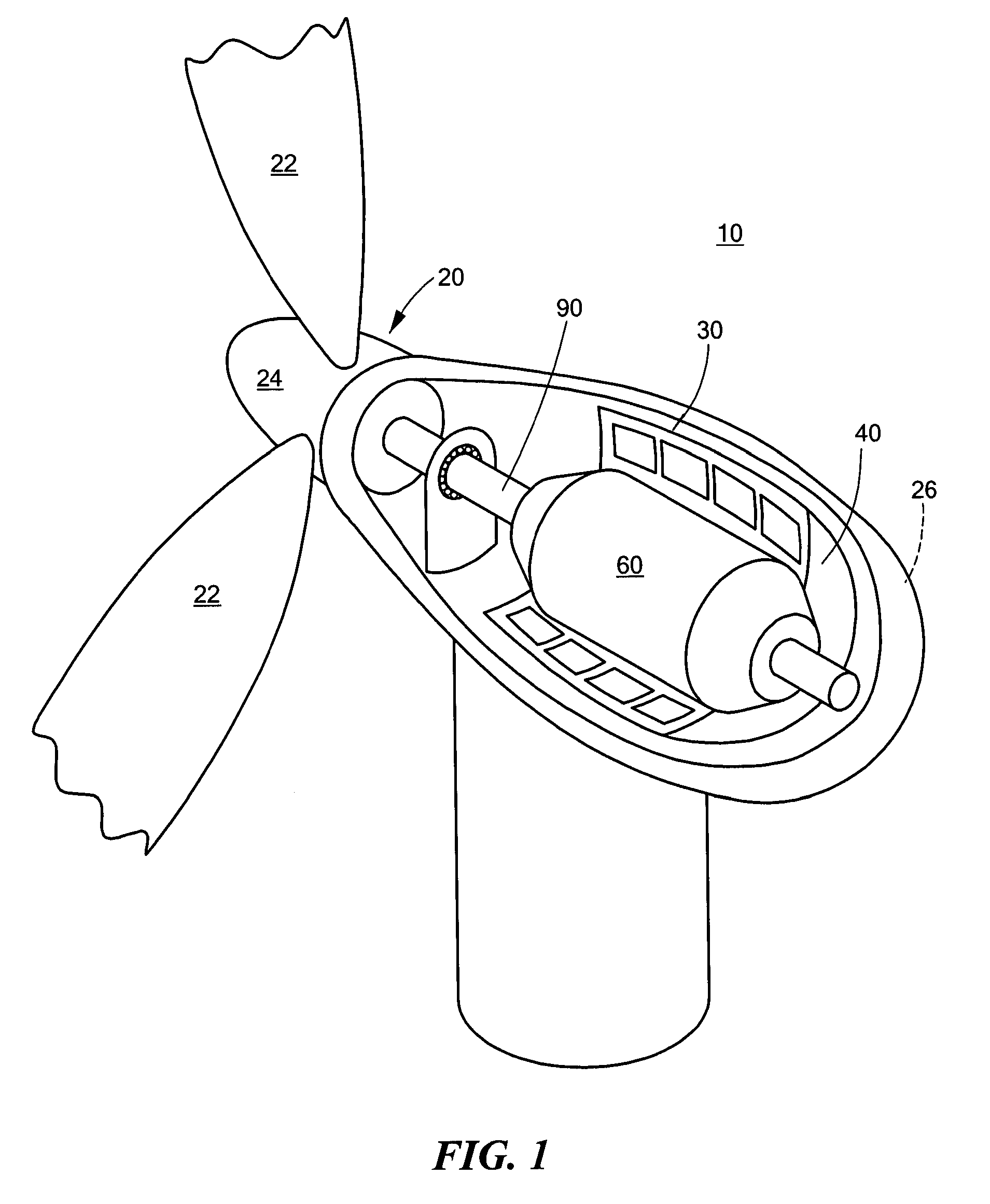
[0026]Referring to FIG. 1, a wind turbine 10 includes a turbine rotor 20 having blades 22 connected to a hub 24. The wind turbine 10 also includes an electrical generator 30 which is driven by a drive shaft 90 that extends between the generator 30 and the hub 24. The generator 30 is housed in a nacelle 26, shown partially cut away with the turbine rotor 20 protruding through an opening in an end of the nacelle 26. As will be described in greater detail below, the generator 30 is configured for use in low frequency applications, and rotates at the same frequency as the turbine rotor 20. For example, in the illustrated embodiment, the generator 30 is configured to operate at around 11 rpm and generate 10 Megawatts of power or more.

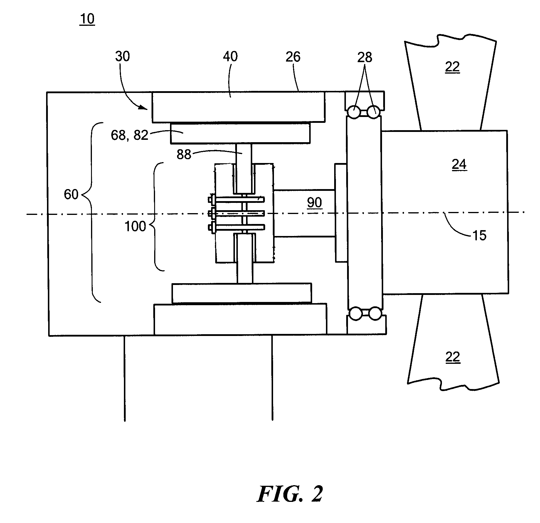
[0027]Referring to FIG. 2, the generator 30 is a direct-drive, synchronous, rotating superconducting machine that includes a rotor assembly 60 containing an HTS field winding and a stator assembly 40 containing a non-superconducting stator winding, for examp...


PUM


Abstract

A rotating machine includes a stator and a rotor configured to rotate within the stator. Rotor windings are supported in the rotor and are formed of a laminated electrical conductor in a single-layer saddle coil configuration. The conductor includes a first support lamina, a second support lamina, an insert including a high temperature superconductor disposed between the first and second support lamina, and a filler material surrounding the insert that bonds the insert to each of the first and second support lamina. At the location between the first support lamina and second support lamina corresponding to the location of the insert, the width dimension of the filler material on each side of the insert is at least 10 percent of a width of the conductor. The conductor is configured to carry at least 600 Amperes per turn and have a C-axis tensile strength of at least 21 MPa.

Description

BACKGROUND OF THE INVENTION[0001]Power generation continues to be an important application of rotating electrical machines. Wind energy is one of the fastest growing sources of electricity around the world, and wind turbines employing rotating electrical machines are used to convert wind energy to usable power. Some conventional wind turbines include a turbine rotor having turbine blades and an output shaft which drive an electrical machine that can supply 3-5 Megawatts of power to the utility power network. However, increased power demand is leading to increased power requirements for each wind turbine. To obtain a wind turbine that can deliver 10 Megawatts or more, a mere scaling up of the size of the conventional geared power train becomes impractical, due at least in part to the size, weight, cost and potential unreliability of a gearbox which can accommodate these requirements.[0002]High temperature superconducting (HTS) coil windings are proposed for use in ultra low speed, di...

Claims


Application Information

Patent Timeline
Patent Type & Authority Patents(United States)
IPC IPC(8): H01L39/24H10N60/20H10N60/01H10N60/80
CPCH02K3/04H01L39/143H02K55/04Y02E40/625H02K7/1838Y02E40/62Y02E10/725Y02E10/72Y02E40/60H10N60/203F16C32/0438H02K3/24H02K7/1892Y10S336/01H10N60/202
Inventor TANNER, MICHAEL A.SNITCHLER, GREGORY L.CARTER, WILLIAM L.PODTBURG, ERIC R.
Owner AMERICAN SUPERCONDUCTOR
Learn More