
Low yield ratio, high strength and high toughness steel plate and method for manufacturing the same

a high strength and high toughness steel plate technology, applied in the field of low yield ratio, high strength and high toughness steel plate and the same manufacturing method, can solve the problems of reducing productivity, increasing manufacturing cost, and extremely low productivity, and achieves the effects of reducing yield ratio, improving low-temperature toughness, and increasing uniform elongation

Active Publication Date: 2014-07-15
JFE STEEL CORP
View PDF22 Cites 4 Cited by
  • Summary
  • Abstract
  • Description
  • Claims
  • Application Information

AI Technical Summary

Benefits of technology

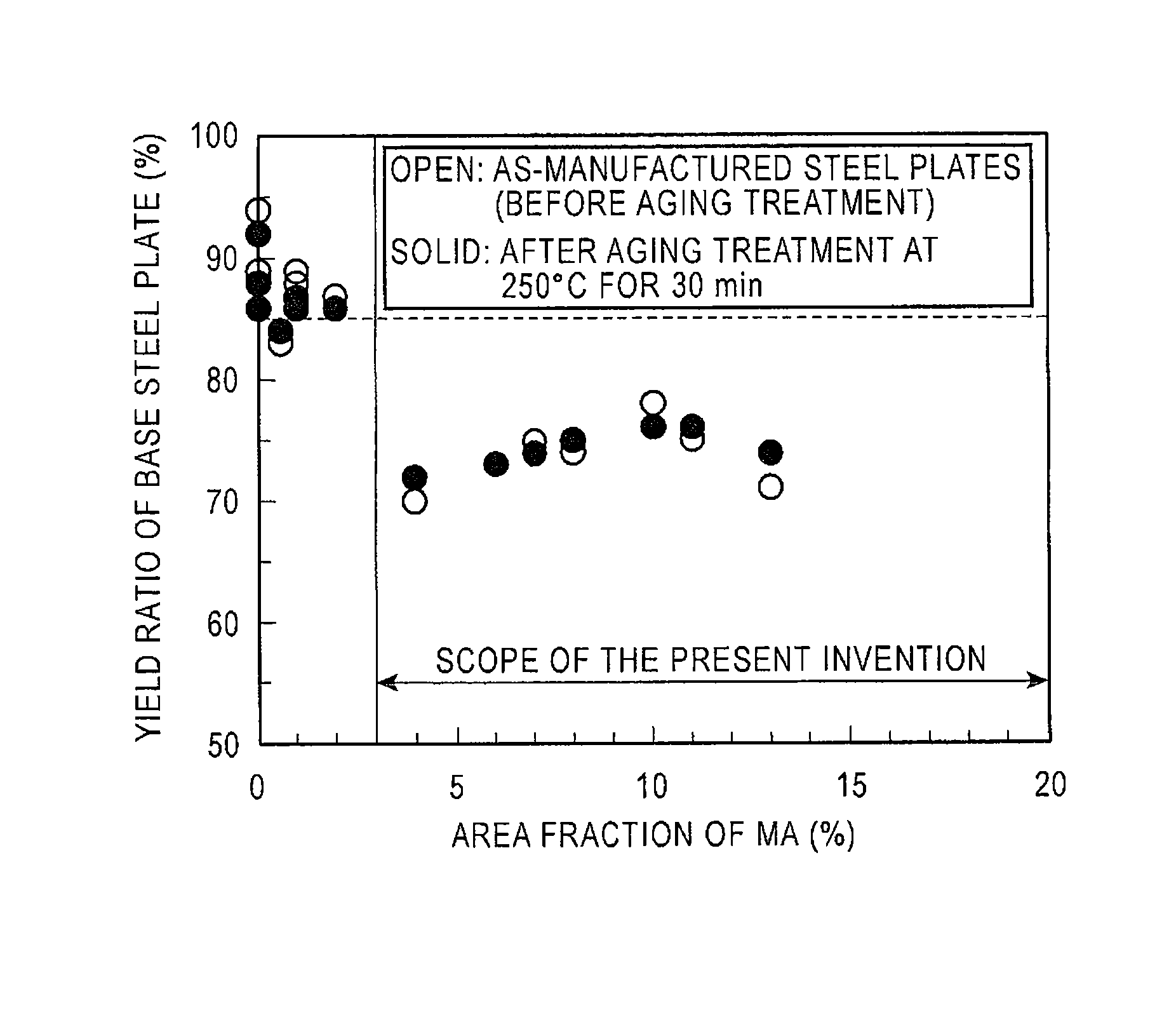
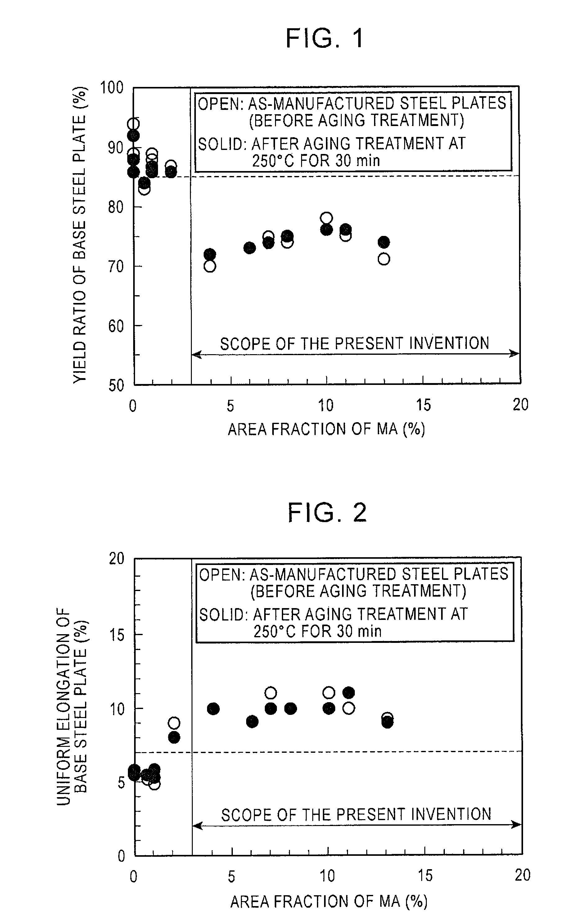
The present invention relates to a steel plate that has several components, including iron, unavoidable impurities, and a specific microstructure. By creating a three-phase microstructure containing soft, bainite, and hard constituents, the steel plate has improved toughness and low-temperature impact resistance. The metallographic microstructure contains 5%-30% bainite, 3%-20% M-A constituent, and the remainder being quasi-polygonal ferrite. This microstructure results in a uniform elongation and yield ratio, making it ideal for applications in earthquake zones.

Problems solved by technology

Therefore, there is a problem in that a reduction in productivity and an increase in manufacturing cost are caused.
Therefore, there is a problem in that productivity is extremely low.
In the technique disclosed in Patent Literature 3, in order to allow the steel material to have a tensile strength of 490 N / mm2 (50 kg / mm2) or more as described in an example, the steel material needs to have an increased carbon content or a composition in which the amount of an added alloying element is increased, which causes an increase in material cost and a problem in that the toughness of a welded heat affected zone is deteriorated.

Method used


Image

  • Low yield ratio, high strength and high toughness steel plate and method for manufacturing the same
  • Low yield ratio, high strength and high toughness steel plate and method for manufacturing the same
  • Low yield ratio, high strength and high toughness steel plate and method for manufacturing the same

Examples


example 1

[0134]Steels (Steels A to J) having compositions shown in Table 1 were processed into slabs by continuous casting and steel plates (Nos. 1 to 16) with a thickness of 20 mm or 33 mm were manufactured from the slabs.

[0135]Each heated slab was hot-rolled, was immediately cooled in an accelerated cooling system of a water-cooled type, and was then reheated in an induction heating furnace or a gas burner furnace. The induction heating furnace and the accelerated cooling system were arranged on the same line.

[0136]Conditions for manufacturing the steel plates (Nos. 1 to 16) are shown in Table 2. Temperatures such as the heating temperature, the finishing rolling temperature, the final (finishing) cooling temperature, and the reheating temperature were the average temperatures of the steel plates. The average temperature was determined from the surface temperature of each slab or steel plate by calculation using a parameter such as thickness and thermal conductivity.

[0137]The cooling rate ...


PUM

PropertyMeasurementUnit
equivalent circle diameteraaaaaaaaaa
temperatureaaaaaaaaaa

Abstract

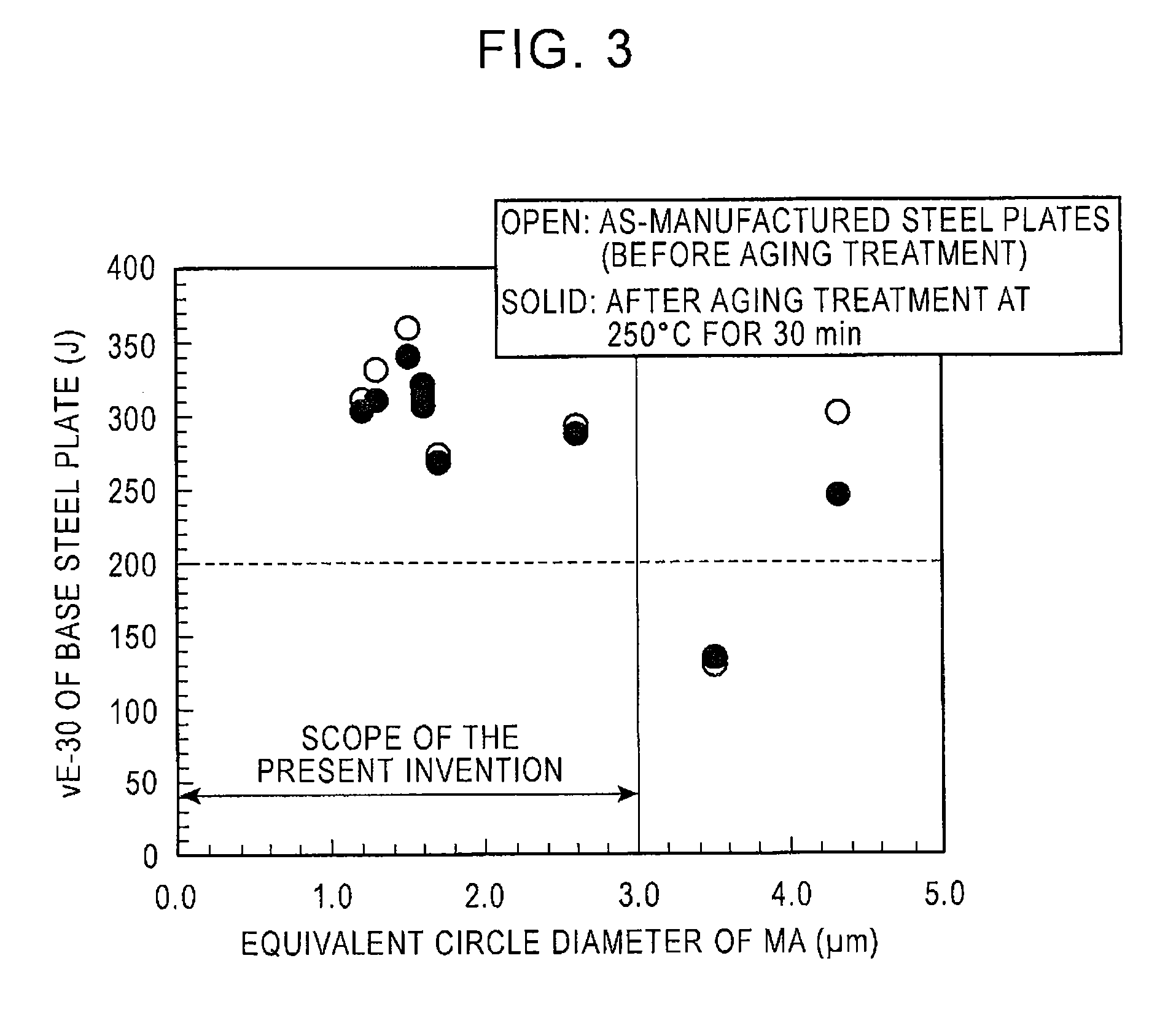
Provided is a low yield ratio, high strength and high toughness steel plate having excellent strain ageing resistance equivalent to API 5L X70 Grade or lower and a method for manufacturing the same. The steel plate has a metallographic microstructure that is a three-phase microstructure including bainite, M-A constituent, and quasi-polygonal ferrite, the area fraction of the bainite being 5% to 70%, the area fraction of the M-A constituent being 3% to 20%, the remainder being the quasi-polygonal ferrite, the equivalent circle diameter of the M-A constituent being 3.0 μm or less. The steel plate has a yield ratio of 85% or less and a Charpy impact test absorbed energy of 200 J or more at −30° C. before or after being subjected to strain ageing treatment at a temperature of 250° C. or lower for 30 minutes or less.

Description

CROSS-REFERENCE TO RELATED APPLICATIONS[0001]This application is the U.S. National Phase application of PCT International Application No. PCT / JP2010 / 067316, filed Sep. 28, 2010, and claims priority to Japanese Patent Application No. 2009-226704, filed Sep. 30, 2009, the disclosures of which PCT and priority applications are incorporated herein by reference in their entireties for all purposes.FIELD OF THE INVENTION[0002]The present invention relates to low yield ratio, high strength and high toughness steel plates suitable for use mainly in the field of line pipes and methods for manufacturing the same and particularly relates to a low yield ratio, high strength and high toughness steel plate having excellent strain ageing resistance and a method for manufacturing the same.BACKGROUND OF THE INVENTION[0003]In recent years, steels for welded structures have been required to have low yield strength and high uniform elongation in addition to high strength and high toughness from an eart...

Claims


Application Information

Patent Timeline
Patent Type & Authority Patents(United States)
IPC IPC(8): C22C38/04C22C38/60
CPCC22C38/02C21D6/005C21D8/0205C21D9/46C21D2211/002C21D2211/005C21D2211/008C22C38/001C22C38/002C22C38/04C22C38/06C22C38/12C22C38/14
Inventor SHIMAMURA, JUNJIISHIKAWA, NOBUYUKISHIKANAI, NOBUO
Owner JFE STEEL CORP
Learn More