
Method and equipment for separating out molten dust in high temperature gas and use thereof

a high temperature gas and molten dust technology, applied in the direction of separation processes, lighting and heating apparatus, furnaces, etc., can solve the problems of dust not being separated out and discharged efficiently, the temperature of the high temperature gas to fall to a lower melting point, etc., to save energy, improve environment, and improve productivity

Active Publication Date: 2014-06-10
CHEN ZHI WEI
View PDF12 Cites 7 Cited by
  • Summary
  • Abstract
  • Description
  • Claims
  • Application Information

AI Technical Summary

Benefits of technology

The present invention provides a method and equipment for efficiently separating out molten dust in high temperature gas and recycling the heat in the high temperature gas. The method includes the steps of passing the high temperature gas carrying molten dust through an adhesive separator and recycling the heat in the high temperature gas through a heat exchanger. This leads to higher temperature of the high temperature gas flowing out the adhesive separator. Using the recycled heat, the gas is heated before entering the adhesive separator, which ensures efficient separation of the molten dust and recycling of the heat. This method improves separation efficiency and avoids block of the heat exchanger, making the process more efficient and effective.

Problems solved by technology

Therefore, the disadvantage in the prior art, i.e. extending the length of the chamber of the adhesive separator may cause the temperature of the high temperature gas to fall to a temperature lower than the melting point of the dust and the dust cannot be separated out and discharge efficiently, can be overcome.

Method used


Image

  • Method and equipment for separating out molten dust in high temperature gas and use thereof
  • Method and equipment for separating out molten dust in high temperature gas and use thereof
  • Method and equipment for separating out molten dust in high temperature gas and use thereof

Examples


embodiment 1

[0093]FIG. 5 illustrates a furnace which uses the method for separating out molten dust in high temperature gas according to one embodiment of the present invention. The furnace includes a centrifugal adhesive separator 1, a filter adhesive separator 10, a dividing wall type heat exchanger 2, a fuel or powder material feeding and controlling device 3, a gas input device 4, a fuel inlet 30 and a gas outlet 50. The outlet of the centrifugal adhesive separator 1 is connected to the gas inlet of the filter adhesive separator 10. The filter separator 10 and the centrifugal adhesive separator 1 share one drain outlet 15. The dividing wall type heat exchanger 2 includes two pipes. Inlet of one of the pipes is connected to the gas outlet of the filter adhesive separator 10. Outlet of this pipe is the gas outlet 50. Inlet of the other pipe of the dividing wall type heat exchanger 2 is connected to the gas input device 4. Outlet of this pipe is connected to the gas inlet 13 of the centrifugal...

embodiment 2

[0107]FIG. 6 illustrates a furnace which uses the method for separating out molten dust in high temperature gas according to one embodiment of the present invention. The furnace includes a centrifugal adhesive separator 1, two regenerative heat exchangers 20, two cyclone furnaces or reaction towers 6, a fuel or powder material feeding and controlling device 3, a gas input device 4, two fuel inlets 30, two gas outlets 50, two valves 51, two gas inverting gates 52, and two fuel inverting gates 53. The chamber of the centrifugal adhesive separator 1 is configured to have a symmetrical structure connected in parallel and then in series. Two sets of regenerators of the regenerative heat exchanger 20 are seated at two sides of the centrifugal adhesive separator 1, each being connected to the gas inlet / gas outlet of the centrifugal adhesive separator 1 via the cyclone furnace or reaction tower 6. The fuel or powder material feeding and controlling device 3 is connected to the cyclone furna...

embodiment 3

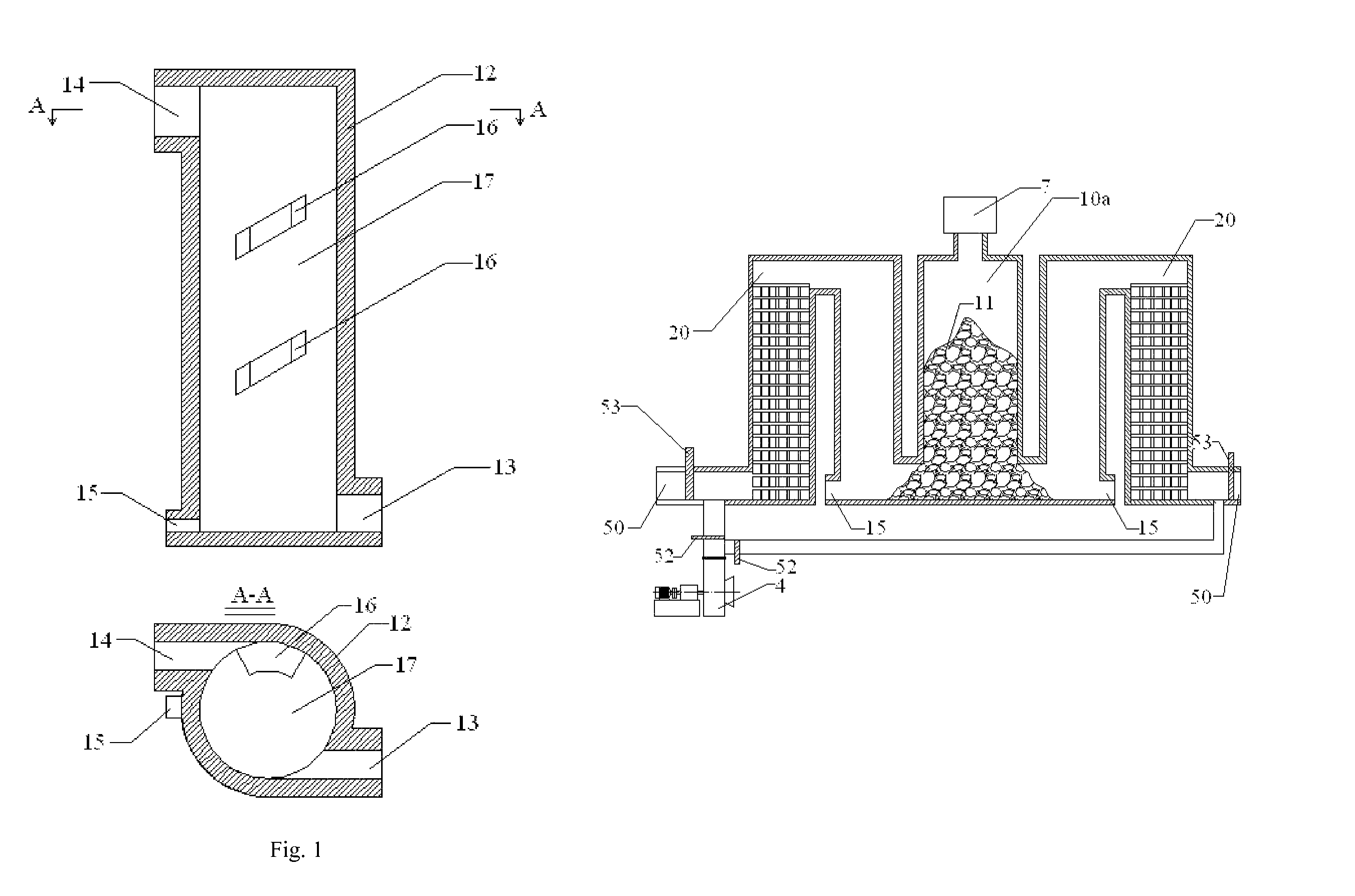
[0115]FIG. 7 illustrates a furnace which uses the method for separating out molten dust in high temperature gas according to one embodiment of the present invention. The furnace includes a filter adhesive separator 10a, two regenerative heat exchangers 20, a granular or bulk material feeding device 7, a gas input device 4, two gas inlets 50, two gas inverting gates 52, and two fuel gas inverting gates 53. The filter adhesive separator 10a uses granular or bulk solid fuel 11 as filter layer. Two sets of regenerators of the regenerative heat exchanger 20 are seated at two sides of the filter adhesive separator 10a. The granular or bulk material feeding device 7 is disposed at the top of the filter adhesive separator 10a. The gas input device 4 is connected to the two sets of regenerators of the regenerative heat exchanger 20, respectively. The gas input device 4 is connected or disconnected to a corresponding regenerator via opening or closing the two gas inverting gates 52. The regen...


PUM

PropertyMeasurementUnit
melting temperatureaaaaaaaaaa
temperatureaaaaaaaaaa

Abstract

A method for separating out molten dust in high temperature gas includes the steps of: passing the high temperature gas carrying molten dust through an adhesive separator, the molten dust adhering to the adhesive separator and separating from the high temperature gas, the molten dust adhering to the inner sidewall flowing downwardly due to the gravity force and discharging; conveying the cleaned high temperature gas into a heat exchanger directly or after heating materials for cooling and discharging; using the heat recycled by the heat exchanger to heat the gas supplied to the adhesive separator; and supplying the gas heated by the heat exchanger into the adhesive separator directly or after further reaction, the heat absorbed from the heat exchanger and the heat generated in the reaction keeping the temperature of the gas flowing out of the adhesive separator higher than the melting point of the dust.

Description

FIELD OF THE INVENTION[0001]The present invention generally relates to methods for separating out molten dust in high temperature gas and, more particularly, relates to a method and equipment for separating out molten metal or mineral dust in high temperature gas and recycling the heat of the gas, as well as the use thereof in solid fuel combustion, solid fuel gasification, solid fuel smelting and metallurgical chemistry reaction.BACKGROUND OF THE INVENTION[0002]In the field of solid fuel combustion, especially in the field of coal combustion, dust in the coal is difficult to be cleaned, which may limit the application of coal. In some furnaces which have strict requirements to the cleanness of the fuel, only expensive liquid fuel or gas fuel can be used.[0003]Chinese patent application number CN 200620012646.2, titled “Clean burner using coal instead of oil”, discloses a method for use in clean combustion of coal and liquid dislagging. In the method for separating out molten dust i...

Claims


Application Information

Patent Timeline
Patent Type & Authority Patents(United States)
IPC IPC(8): B01D45/00
CPCB01D45/08B01D45/12B01D45/16B01D46/0027C10J3/46C03B5/167C03B5/235C03B5/237C21B13/0006C21B11/00F27D17/008C10J2300/0956C10J2300/0976B01D50/20
Inventor CHEN, ZHI-WEI
Owner CHEN ZHI WEI
Learn More