
Method for making a fuel cell

a fuel cell and fuel cell technology, applied in the manufacture of cell components, final product products, electrochemical generators, etc., can solve the problems of limiting the gas diffusion rate into the interior of the thick anode, limiting fuel utilization, and difficulty in providing adequate electrical contact between each cell and its metal

Active Publication Date: 2014-05-06
NASA
View PDF18 Cites 5 Cited by
  • Summary
  • Abstract
  • Description
  • Claims
  • Application Information

AI Technical Summary

Benefits of technology

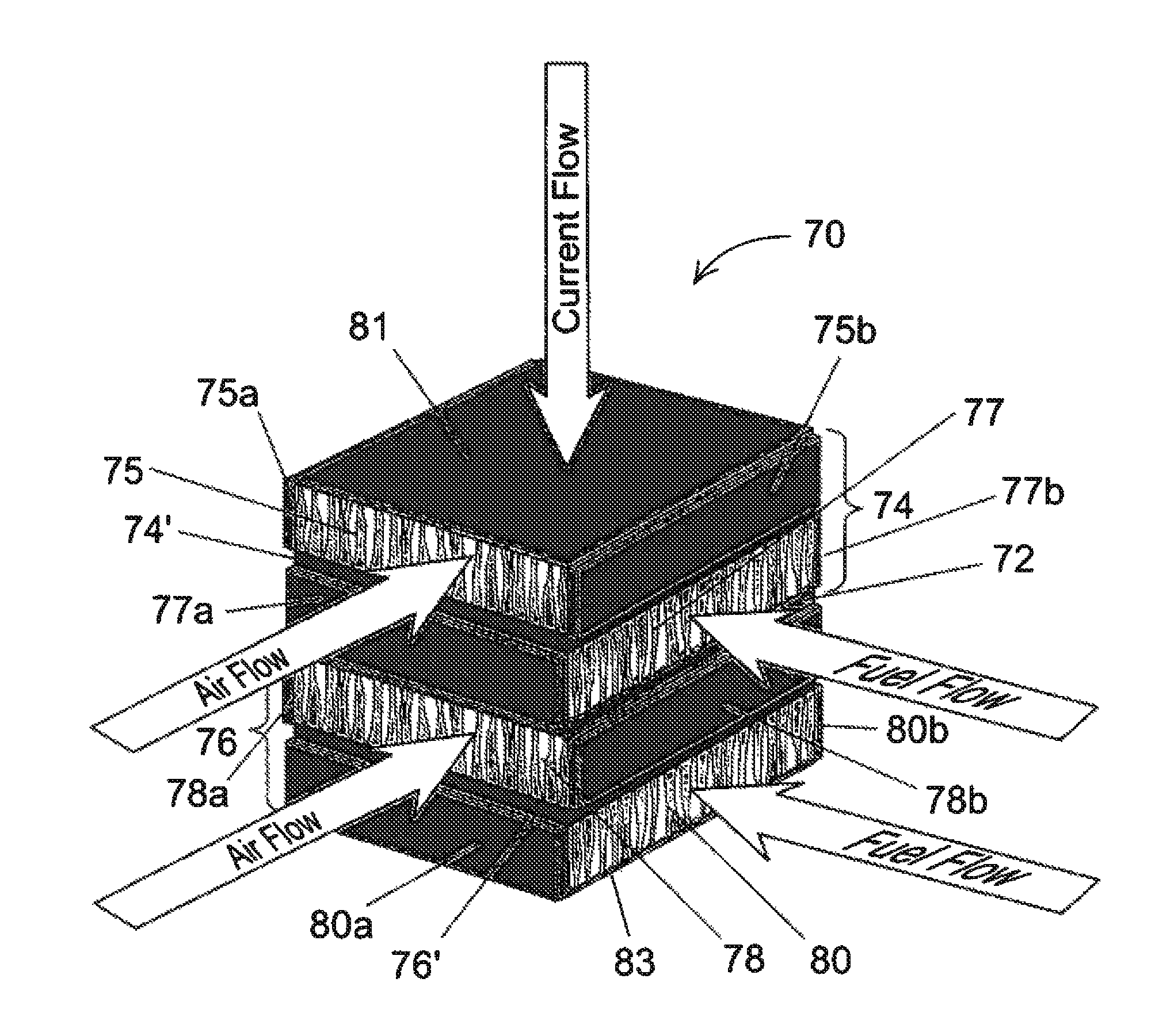
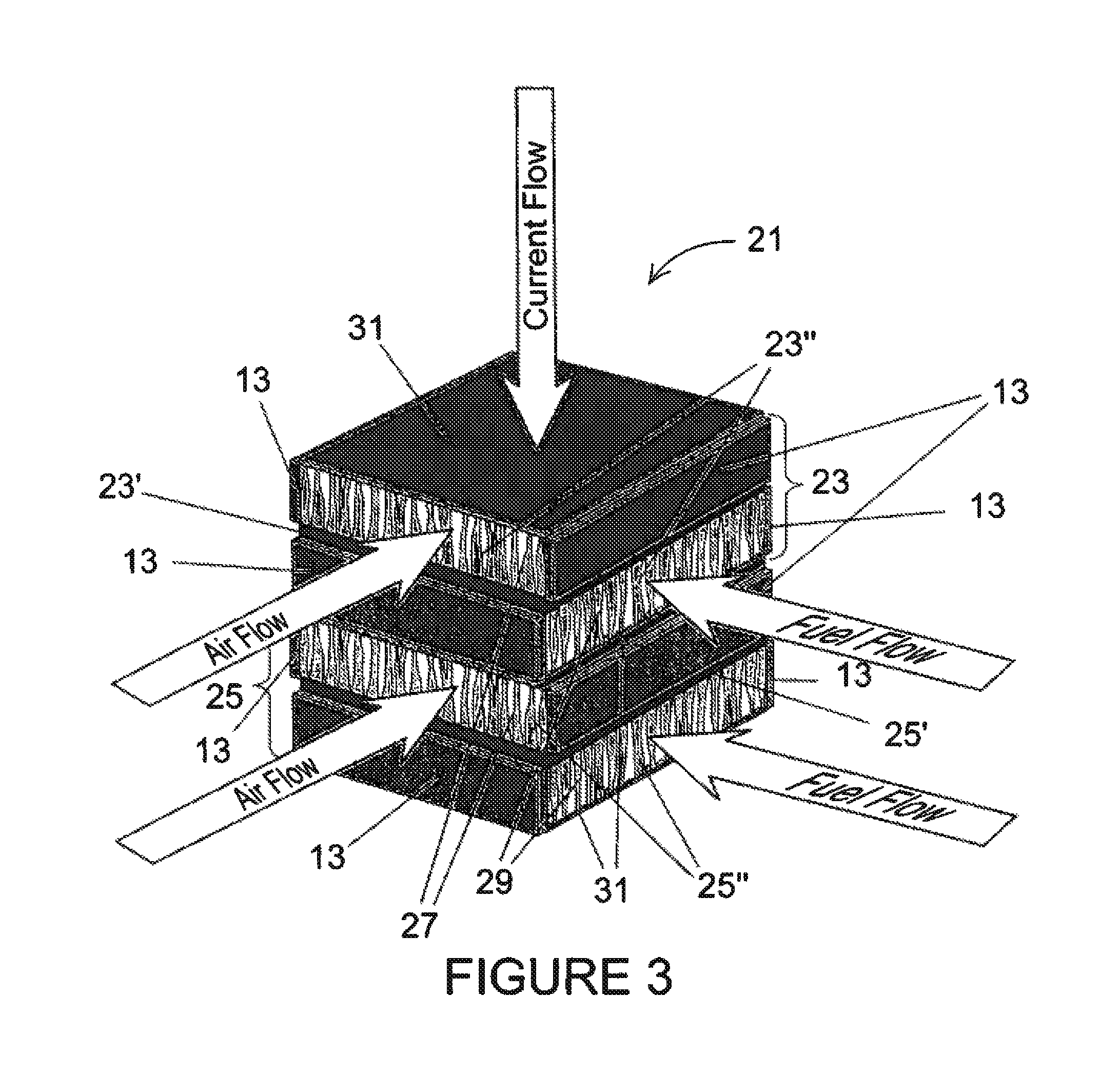
The patent text describes a method and structure for making a fuel cell using a solid oxide monolith framework. The monolith includes a first electrode scaffold with graded pores, a second electrode scaffold with graded pores, and a thin electrolyte layer between the two scaffolds. The method involves impregnating the graded pores of the first scaffold with a liquid metal precursor material and impregnating the graded pores of the second scaffold with an active cathode material. The resulting fuel cell structure has symmetrical bi-electrodes and a high surface area for improved fuel particle diffusion and reaction. The technical effects of this structure include improved fuel cell performance and efficiency.

Problems solved by technology

The major challenges of the ASC technology are: cell fabrication and operational reliability; cell electrical contact to the interconnect; and sealing of the cell-to-metal interconnect.
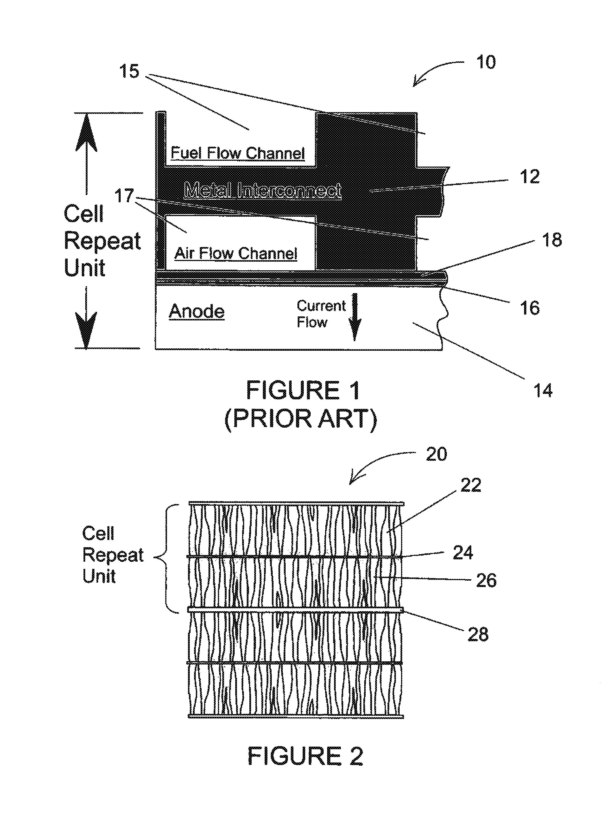
The difficulties in ASC cell and stack fabrication and operation include: 1) shrinkage matching of the thick NiO—YSZ cermet anode and the thin YSZ electrolyte layers during the sintering process; 2) production of flat cell parts for assembly into fuel cell stacks; 3) as the nickel component of the anode cermet is reduced from NiO to Ni metal, the resultant volume change can generate stresses within the anode, sometimes leading to failure of the thin YSZ electrolyte; 4) the anode is sensitive to leaks of oxygen that can cause oxidation of the Ni metal resulting in a sudden expansion of the anode and failure of the cell; 5) provision of sufficient anode thickness to support the electrolyte creates a long pathway for reactant and can lead to diffusion problems in the anode making it hard to achieve high fuel utilization required for high-power commercial applications; 6) ASC cells are fragile and cannot tolerate the high compressive loading that is required for some of the compression type seals used with the ASC stacking technology; 7) pore channels of the bulk anode must be relatively narrow in order to give the anode adequate strength, but this limits the rate of gas diffusion into the interior of the thick anode and limits fuel utilization; and 8) the grooved metal interconnects are on the order of 2-3 mm thick and contribute more than 70% of the mass of a stack.
The most critical technical challenges facing all planar SOFC stack developers are the difficulties in providing adequate electrical contact between each cell and its metal interconnect and gas-tight seals.

Method used


Image

  • Method for making a fuel cell
  • Method for making a fuel cell
  • Method for making a fuel cell

Examples


second embodiment

A Second Embodiment

[0062]The inventors envision a second embodiment of their solid oxide fuel cell stack invention wherein the invention is modified as described below for the purpose of providing crew life support for NASA exploration missions including surface habitat and EVA suit implementation. More specifically, the present invention can be modified and optimized to perform electrolysis on the CO2 so as to produce breathable oxygen in CO2 rich settings, such as the surface of Mars.

[0063]Modification and optimization of the present invention would include the use of electrocatalysts tailored for electrolysis of CO2. The advantages would include low weight, durability, and high efficiency and specific power density.

[0064]The atmosphere on Mars, for example, is 95% CO2, making it an obvious source of O2. A single solid oxide fuel cell has successfully demonstrated the production of O2 from the electrolysis of CO2. The products of the electrolysis are pure O2 and CO and the power r...

third embodiment

A Third Embodiment

[0065]The inventors envision a third embodiment of their solid oxide fuel cell stack invention wherein the invention is modified as described below for the purpose of providing crew life support for NASA exploration missions including surface habitat and EVA suit implementation. More specifically, the present invention can be modified and optimized to perform electrolysis on the H2O present in the astronaut suits so as to produce breathable oxygen. Said fuel cells is also reversible and able to generate power from the stored H2 and O2 are used as fuel.

[0066]Modification and optimization of the present invention would include the use of electrocatalysts tailored for electrolysis of H2O or CO2. The advantages would include low weight, durability, and high efficiency and specific power density.

[0067]Heretofore, only fuel cells having very thick YSZ electrolytes, on the order of 300 to 600 microns thick, have been demonstrated (see AIAA 2000-1068 “Update on the Oxygen ...


PUM

PropertyMeasurementUnit
thicknessaaaaaaaaaa
thicknessaaaaaaaaaa
thickaaaaaaaaaa

Abstract

The invention is a novel solid oxide fuel cell (SOFC) stack comprising individual bi-electrode supported fuel cells in which an electrolyte layer is supported between porous electrodes. The porous electrodes may be made from graded pore ceramic tape that has been created by the freeze cast method followed by freeze-drying. Each piece of graded pore tape later becomes a graded pore electrode scaffold that, subsequent to sintering, is made into either an anode or a cathode. The electrode scaffold comprising the anode includes a layer of liquid metal. The pores of the electrode scaffolds gradually increase in diameter as the layer extends away from the electrolyte layer. As a result of this diameter increase, any forces that would tend to pull the liquid metal away from the electrolyte are reduced while maintaining a diffusion path for the fuel. Advantageously, the fuel cell of the invention may utilize a hydrocarbon fuel without pre-processing to remove sulfur.

Description

CROSS-REFERENCE TO RELATED APPLICATIONS[0001]This application claims priority from and is a continuation-in-part application of U.S. Ser. No. 12 / 860,210, filed on Aug. 20, 2010, entitled “METHOD FOR MAKING A FUEL CELL”, which is a divisional of U.S. patent application Ser. No. 11 / 228,184, filed on Sep. 16, 2005, entitled “MONOLITHIC SOLID OXIDE FUEL CELL STACK WITH SYMMETRICAL, BI-ELECTRODE SUPPORTED CELLS”, which are hereby incorporated by reference in their entirety.ORIGIN OF THE INVENTION[0002]The invention described herein was made by employees of the United States Government and may be manufactured and used by or for the Government for Government purposes without the payment of any royalties thereon or therefore.FIELD OF THE INVENTION[0003]The present invention relates generally to fuel cells and fuel cell stacks, and more particularly to high power density solid-oxide fuel cells and the fabrication of unitized stacks of solid oxide fuel cells created from monolithic ceramic fr...

Claims


Application Information

Patent Timeline
Patent Type & Authority Patents(United States)
IPC IPC(8): H01M4/48H01M8/00H01M8/10
CPCH01M8/1206H01M4/8846H01M8/2425H01M2008/1293Y02E60/525H01M4/8885Y02E60/521H01M8/2435H01M8/1231H01M8/2404Y02E60/50Y02P70/50
Inventor CABLE, THOMAS LSETLOCK, JOHN AFARMER, SERENE C
Owner NASA
Learn More