
Vapor chamber and method for manufacturing the same

a technology of vapor chamber and heat dissipation chamber, which is applied in the direction of lighting, heating apparatus, electrical equipment casings/cabinets/drawers, etc., can solve the problems of increasing the cost of thermal interface materials. , to achieve the effect of reducing thermal resistance, saving thermal interface materials cost, and reducing thermal conductivity

Active Publication Date: 2014-03-18
PEGATRON
View PDF32 Cites 11 Cited by
  • Summary
  • Abstract
  • Description
  • Claims
  • Application Information

AI Technical Summary

Benefits of technology

The present invention integrates the vapor chamber and metal casing of an electronic device, which reduces thermal resistance and improves thermal conductivity without using a thermal interface material. A ceramic layer, waterproof layer, and powder porous wick structure layer are formed on the inner walls of the vapor chamber for better cooling using water as the working fluid. Additionally, an electrical-insulating heat-conducting ceramic layer prevents electrochemistry corrosion caused by standard potential difference between different materials. Overall, the invention improves heat dissipating efficiency and provides better protection for the electronic device.

Problems solved by technology

Therefore, an inner space of a casing becomes smaller, and fans are limited in order to reduce noise so that thermal management of the electronic devices becomes more and more serious and needs to be solved.
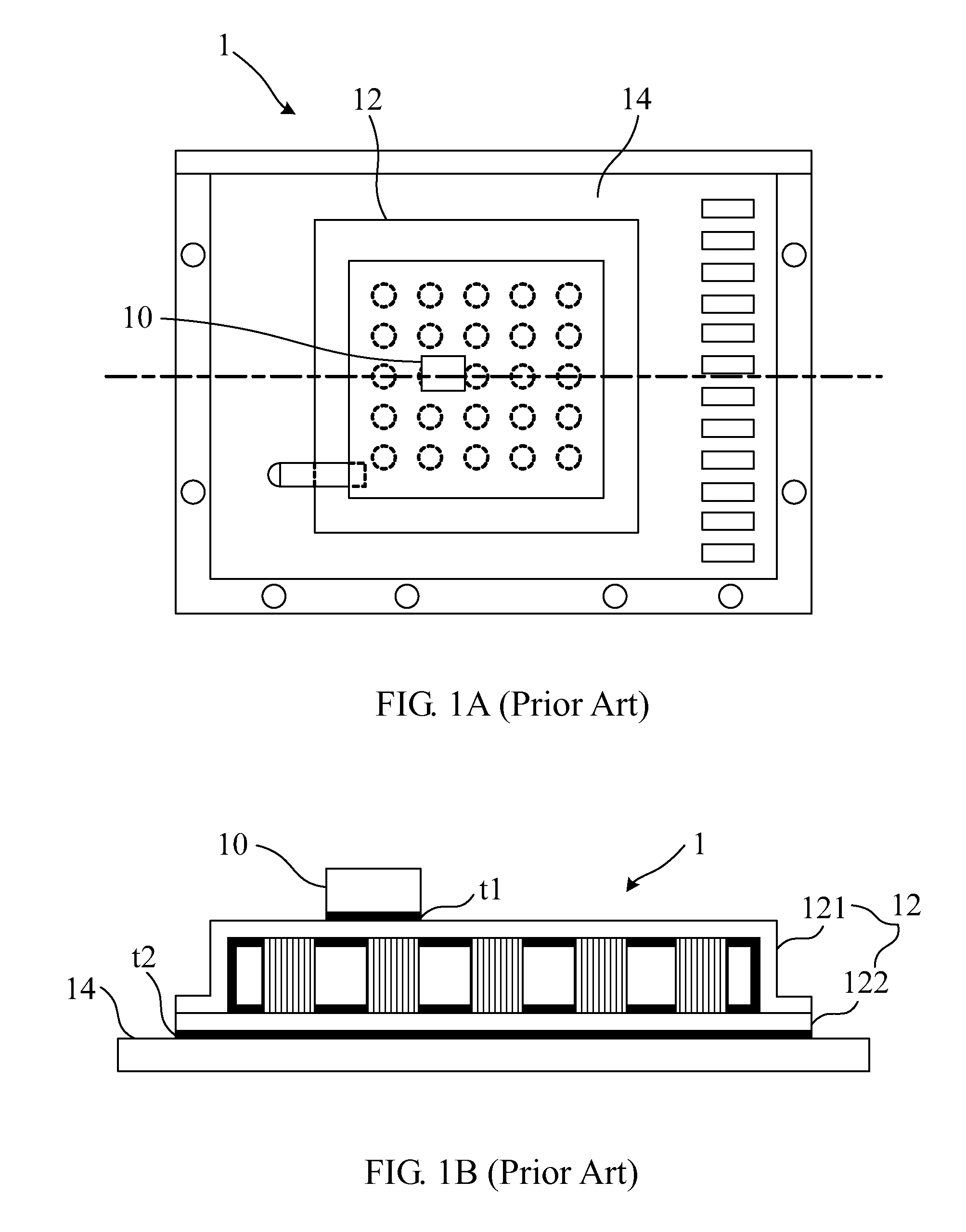
However, the heat dissipating mode in the conventional electronic device 1 still has a great of disadvantages.
Therefore, the heat generated by the power transistor element 10 of the electronic device 1 fails to be effectively dissipated, and the operating temperature thereof is still higher, which greatly reduces reliability and the lifespan of the electronic device 1.

Method used


Image

  • Vapor chamber and method for manufacturing the same
  • Vapor chamber and method for manufacturing the same
  • Vapor chamber and method for manufacturing the same

Examples


Embodiment Construction

[0024]In one embodiment of this invention, a vapor chamber is provided. In a practical application, the vapor chamber is used in an electronic device and is integrated with a metal casing of the electronic device. The electronic device can be a digital camera, a cell phone, a notebook computer, or a desktop computer. However, the invention is not limited thereto. The metal casing can be made of a material selected from a group consisting of aluminum-magnesium alloy, aluminum alloy, magnesium alloy, aluminum, steel, and iron. However, the invention is not limited thereto.

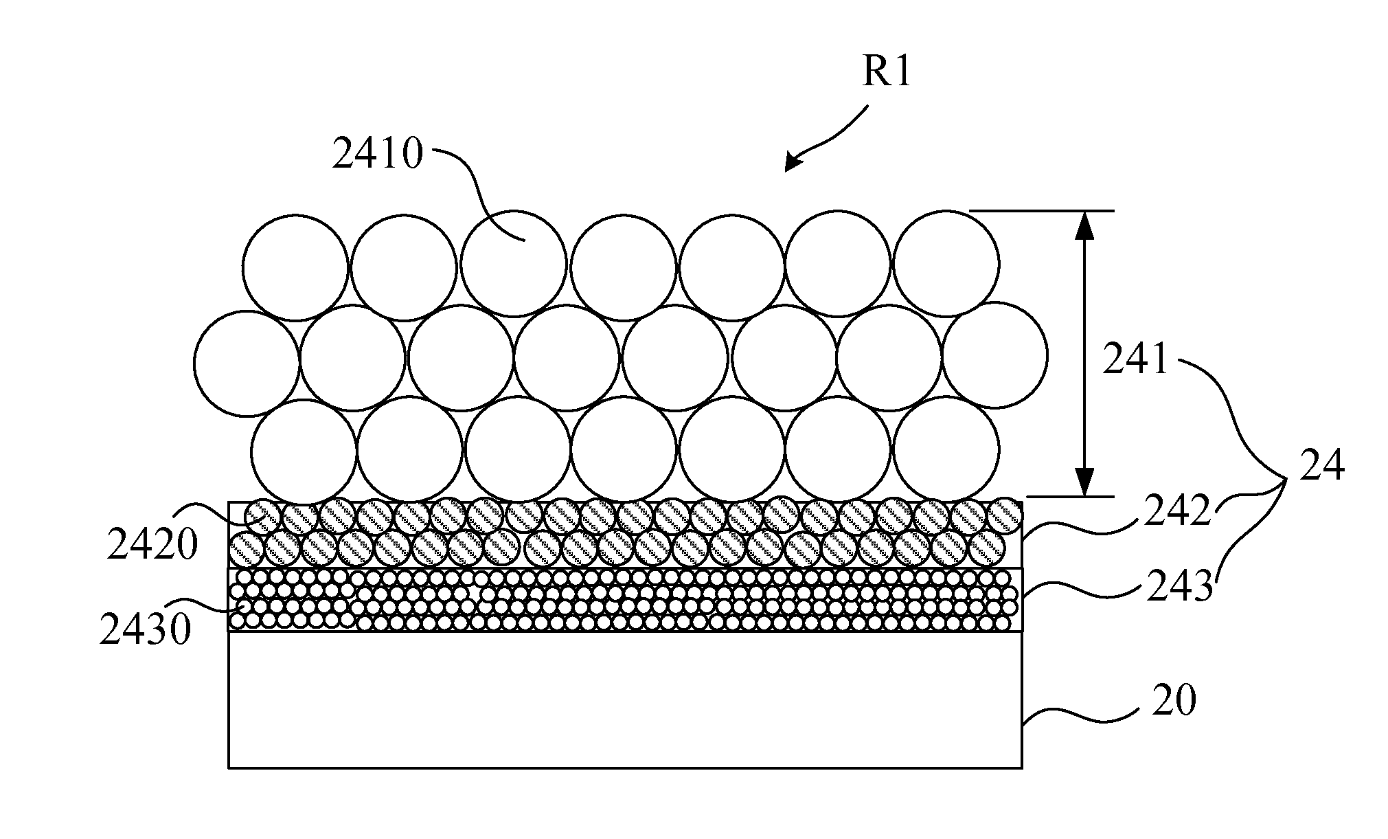
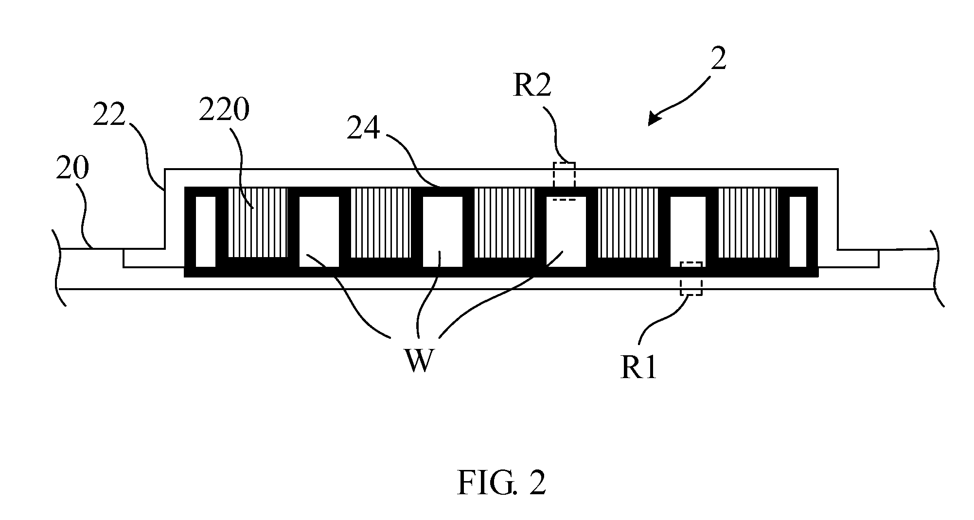
[0025]FIG. 2 is a sectional view showing a vapor chamber according to the embodiment of the invention. In FIG. 2, an upper cover 22 of a vapor chamber 2 is disposed on inner walls of a metal casing 20 of an electronic device to define a containing space. A thermal spray layer 24 is formed on inner walls of the containing space. In detail, the thermal spray layer 24 is formed on the metal casing 20 and inner walls of ...


PUM

PropertyMeasurementUnit
porosityaaaaaaaaaa
porosityaaaaaaaaaa
porosityaaaaaaaaaa

Abstract

The vapor chamber is used in an electronic device. The electronic device includes a metal casing. The vapor chamber includes an upper cover, a working fluid, a waterproof layer, and a wick structure layer. The upper cover is disposed on inner walls of the metal casing to define a containing space. The working fluid is filled into the containing space. The waterproof layer is formed on inner walls of the containing space. The wick structure layer is formed on the waterproof layer.

Description

CROSS-REFERENCE TO RELATED APPLICATIONS[0001]This Non-provisional application claims priority under 35 U.S.C. §119(a) on Patent Application No(s). 099101497 filed in Taiwan, Republic of China Jan. 20, 2010, the entire contents of which are hereby incorporated by reference.BACKGROUND OF THE INVENTION[0002]1. Field of the Invention[0003]This invention relates to heat dissipation and, more particularly, to a vapor chamber effectively saving a cost of thermal interface materials and a base of the vapor chamber and a method for manufacturing the same.[0004]2. Description of the Related Art[0005]In recent years, heat dissipation of the electronic device is gradually interested as an electronic device is gradually developed to be light, slim, short, and small. Particularly, present consuming electronic products, such as a digital camera, a cell phone, a notebook computer and so on, have more complicated functions and include more and more power transistor elements. Therefore, an inner spac...

Claims


Application Information

Patent Timeline
Patent Type & Authority Patents(United States)
IPC IPC(8): H05K7/20B23P15/26F28D15/04
CPCC23C28/30F28F2245/00F28F2265/24H01L23/427F28D15/046F28F2265/16F28D15/0233Y10T29/4935H01L2924/0002Y10T29/49353H01L2924/00
Inventor LIU, JUEI-KHAICHUNG, CHAO-TSAI
Owner PEGATRON
Learn More