
Method of manufacturing a magnetic recording medium

a manufacturing method and magnetic recording technology, applied in the direction of vacuum evaporation coating, coating, coating part of support with magnetic layer, etc., can solve the problems of degrading magnetic performance, extremely difficult to leave a protective film with a uniform thickness, etc., and achieve excellent productivity and simple process

Inactive Publication Date: 2014-03-04
FUJI ELECTRIC CO LTD
View PDF12 Cites 0 Cited by
  • Summary
  • Abstract
  • Description
  • Claims
  • Application Information

AI Technical Summary

Benefits of technology

The present invention provides a method for manufacturing a magnetic recording medium that does not damage its magnetic performance during production, resulting in a high quality product with excellent performance and productivity. This method is simple and does not require an flattening process.

Problems solved by technology

As a result, degradation of magnetic performance occurs due to damage and oxidation of the magnetic recording layer by the etching process and corrosion of the magnetic recording layer by a residual component of an etching gas or etching solution.
While this may be assumed not to eliminate the entire protective film, leaving a very thin film, it is extremely difficult to leave a protective film with a uniform thickness, eliminating unevenness.

Method used


Image

  • Method of manufacturing a magnetic recording medium
  • Method of manufacturing a magnetic recording medium
  • Method of manufacturing a magnetic recording medium

Examples


example 1

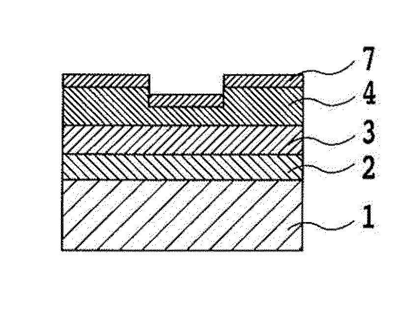
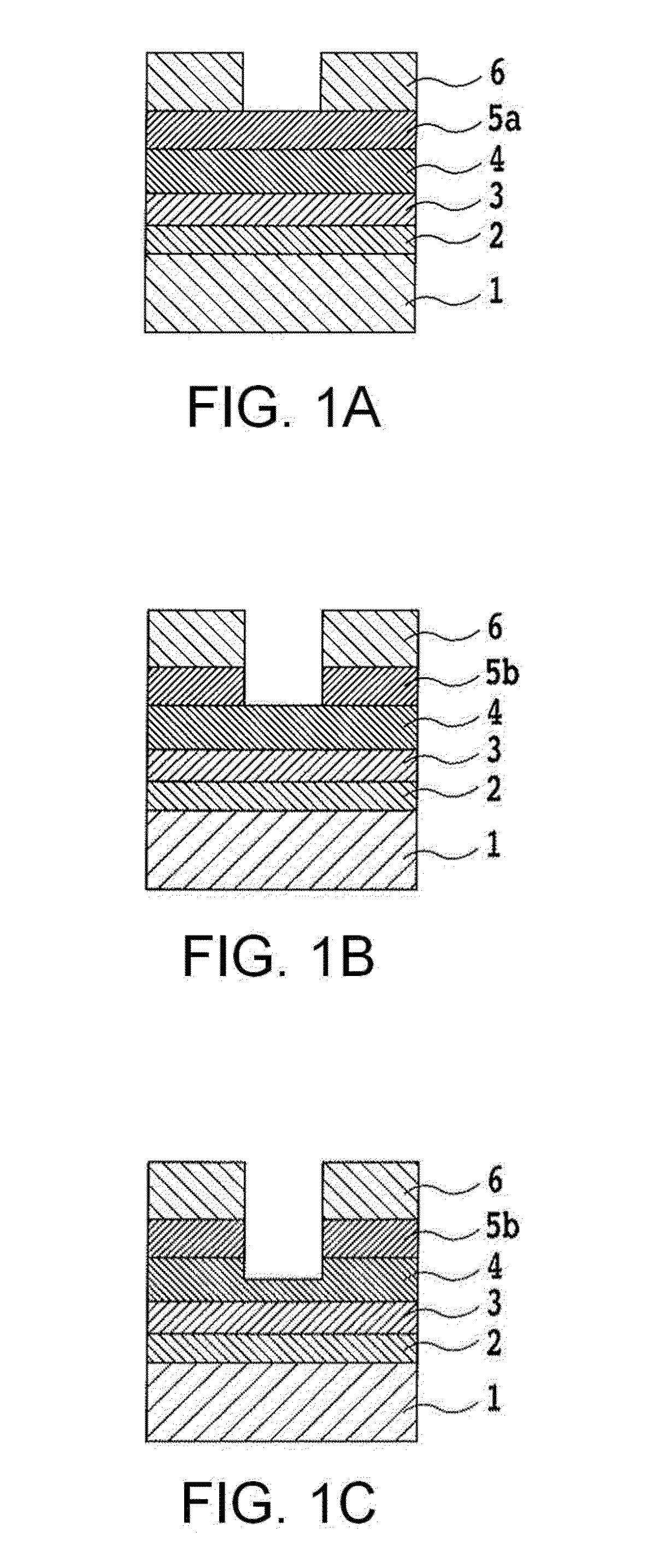
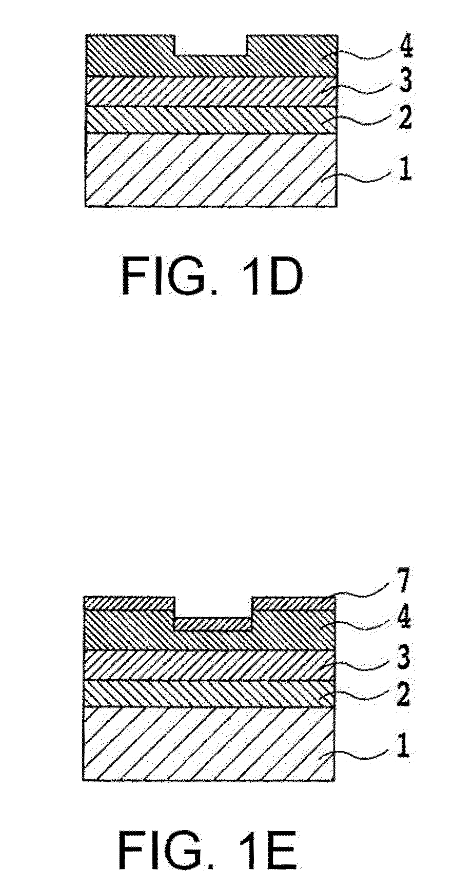
[0051]The substrate 1 used was a chemically reinforced glass substrate (N-5 glass substrate manufactured by HOYA Corporation, for example) having a smooth surface. By means of a sputtering method, the following were deposited: a soft magnetic layer 2 of CoZrNb 200 nm thick, a crystal orientation control layer 3 of NiFeNb 3 nm thick, and ruthenium 14 nm thick thereon.

[0052]Then, CoCrPt—SiO2 was deposited to form a first magnetic layer of a granular magnetic layer having nonmagnetic grain boundaries composed of SiO2. Subsequently, a second magnetic layer of CoCrPt alloy 10 nm thick was deposited to obtain a non-granular magnetic layer.

[0053]Next, a carbon layer 10 nm thick was deposited to form a mask protective film 5a by way of sputtering. Thus, a raw medium was produced having a soft magnetic layer 2, a crystal orientation control layer 3, a first magnetic layer, a second magnetic layer, and a mask protective film 5a laminated on a substrate 1.

[0054]Then, the raw substrate having t...

example 2

[0061]A DTM was manufactured in the same procedure as in Example 1 except that the step of removing the protective mask was carried out by ultraviolet light irradiation in an environment under a reduced pressure instead of in the environment of nitrogen gas. The step in Example 2 was carried out using a xenon excimer lamp with a principal wavelength of 172 nm disposed 2 mm away from the substrate in a chamber at a pressure of 20 Pa. Since the ultraviolet light irradiation was conducted in an environment under reduced pressure, the decomposed carbon was exhausted, preventing re-adhesion in this Example 2 as well. Evaluation results for the signals from the obtained magnetic recording medium are given in Table 1 together with the results for Example 1.


PUM

PropertyMeasurementUnit
wavelengthaaaaaaaaaa
pressureaaaaaaaaaa
thicknessaaaaaaaaaa

Abstract

A method of manufacturing a magnetic recording medium, includes, in the order recited, the steps of forming a mask protective film composed of carbon on a magnetic layer; forming a resist with a predetermined pattern on the mask protective film; forming a protective mask by etching the mask protective film using the resist as a mask; forming protrusions and recesses on a magnetic layer by etching the magnetic layer using the resist and the protective mask as masks; removing the protective mask, including removing the mask protective film comprised of carbon, using ultraviolet light with a principal wavelength not longer than 340 nm; and forming a protective layer on the magnetic layer having the protrusions and recesses formed thereon.

Description

CROSS-REFERENCE TO RELATED APPLICATION[0001]This application is based on, and claims priority from, Japanese Patent Application No. 2008-293581, filed on Nov. 17, 2008, the contents of which are incorporated herein by reference in their entirety.BACKGROUND OF THE INVENTION[0002]1. Field of the Invention[0003]The present invention relates to a method of manufacturing a magnetic recording medium.[0004]2. Description of the Related Art[0005]Among various efforts to enhance recording density of magnetic recording media, a discrete track medium (hereinafter referred to as DTM) has been proposed in which irregularities (protrusions and recesses) are formed along a track direction on the recording surface to reduce magnetic interference between tracks and increase track density, thereby enhancing the recording density.[0006]In some of the techniques for the discrete track medium, a pattern of protrusions and recesses is formed on a resist, and using the resist pattern by way of etching tec...

Claims


Application Information

Patent Timeline
Patent Type & Authority Patents(United States)
IPC IPC(8): B44C1/22
CPCG11B5/855
Inventor KURATA, NOBORU
Owner FUJI ELECTRIC CO LTD
Learn More