Solid-state imaging device, method for manufacturing solid-state imaging device, and electronic apparatus
a solid-state imaging and imaging device technology, applied in the manufacture of final products, basic electric elements, radiation control devices, etc., can solve the problems of affecting difficult to disperse, and occurrence of dark current due to crystal defects, etc., to achieve suppressed effects, the image quality of the resulting image is reduced, and the effect of reducing the amount o
Inactive Publication Date: 2014-02-11
SONY CORP
View PDF5 Cites 7 Cited by
- Summary
- Abstract
- Description
- Claims
- Application Information
AI Technical Summary
Benefits of technology
The solution enhances image quality by reducing dark current and color mixing, improving sensitivity, and maintaining high crystallinity, enabling effective light reception even in low-light conditions.
Problems solved by technology
Consequently, an occurrence of a dark current due to crystal defects may become significant.
In this case, it is difficult to disperse.
Consequently, in the above description, isolation between pixels is not sufficient and, thereby, color mixing may occur between pixels, so as to degrade the image quality of the resulting image.
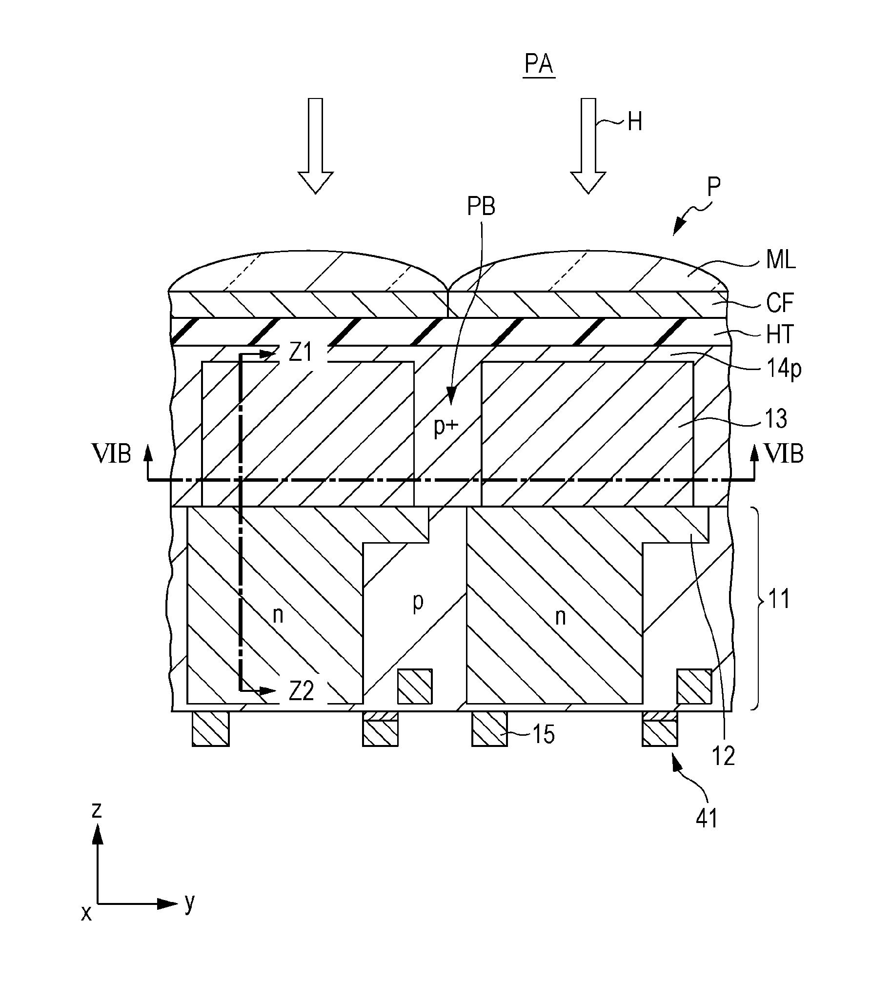
Moreover, the side wall of the photoelectric conversion portion constituting the pixel is exposed and, thereby, an interface state is formed there, and an occurrence of a dark current may become large because of, for example, release of trapped carriers.
In particular, in the case where the etching treatment is performed by the RIE method, damage to the crystal due to ion irradiation becomes significant and, thereby, an occurrence of a dark current becomes large.
Method used
View moreImage
Smart ImageViewing Examples
Examples
first embodiment (
1. First embodiment (Formation of pixel isolation doped through ion implantation (backside-illumination type+CF))
second embodiment (
2. Second embodiment (Formation of pixel isolation doped through lateral growth (backside-illumination type+CF))
third embodiment (
3. Third embodiment (Formation of pixel isolation (non-doped) through composition control)
Login to View More PUM
 Abstract
A solid-state imaging device is provided with a pixel region in which a plurality of pixels including photoelectric conversion films are arrayed and pixel isolation portions are interposed between the plurality of pixels, wherein the photoelectric conversion film is a chalcopyrite-structure compound semiconductor composed of a copper-aluminum-gallium-indium-sulfur-selenium based mixed crystal or a copper-aluminum-gallium-indium-zinc-sulfur-selenium based mixed crystal and is disposed on a silicon substrate in such a way as to lattice-match the silicon substrate concerned, and the pixel isolation portion is formed from a compound semiconductor subjected to doping concentration control or composition control in such a way as to become a potential barrier between the photoelectric conversion films disposed in accordance with the plurality of pixels.
Description
BACKGROUND OF THE INVENTION[0001]1. Field of the Invention[0002]The present invention relates to a solid-state imaging device, a method for manufacturing the solid-state imaging device, and an electronic apparatus.[0003]2. Description of the Related Art[0004]Electronic apparatuses, e.g., digital video cameras and digital steel cameras, include solid-state imaging devices. For example, complementary metal oxide semiconductor (CMOS) type image sensors and charge coupled device (CCD) type image sensors are included as the solid-state imaging devices.[0005]In the solid-state imaging device, a plurality of pixels are arrayed on a surface of a semiconductor substrate. In each pixel, a photoelectric conversion portion is disposed. The photoelectric conversion portion is, for example, a photodiode, and generates a signal charge by receiving light incident through an externally attached optical system with a light-receiving surface and effecting photoelectric conversion.[0006]In the case whe...
Claims
Login to View More Application Information
Patent Timeline
 Patent Type & Authority Patents(United States)
IPC IPC(8): H01L31/00H04N25/00
CPCH01L31/0322Y02E10/541H01L27/1463H01L27/1464H01L27/14687H01L27/14625Y02P70/50H01L27/14636
Inventor TODA, ATSUSHI
Owner SONY CORP
Features
- R&D
- Intellectual Property
- Life Sciences
- Materials
- Tech Scout
- Unparalleled Data Quality
- Higher Quality Content
- 60% Fewer Hallucinations
Learn More Browse by: Latest US Patents, China's latest patents, Technical Efficacy Thesaurus, Application Domain, Technology Topic, Popular Technical Reports.
© 2025 PatSnap. All rights reserved.Legal|Privacy policy|Modern Slavery Act Transparency Statement|Sitemap|About US| Contact US: help@patsnap.com


