Delay test circuitry
a delay generation and circuit technology, applied in the direction of electronic circuit testing, measurement devices, instruments, etc., can solve the problem that the error-capture circuitry may output an error
- Summary
- Abstract
- Description
- Claims
- Application Information
AI Technical Summary
Benefits of technology
Problems solved by technology
Method used
Image
Examples
Embodiment Construction
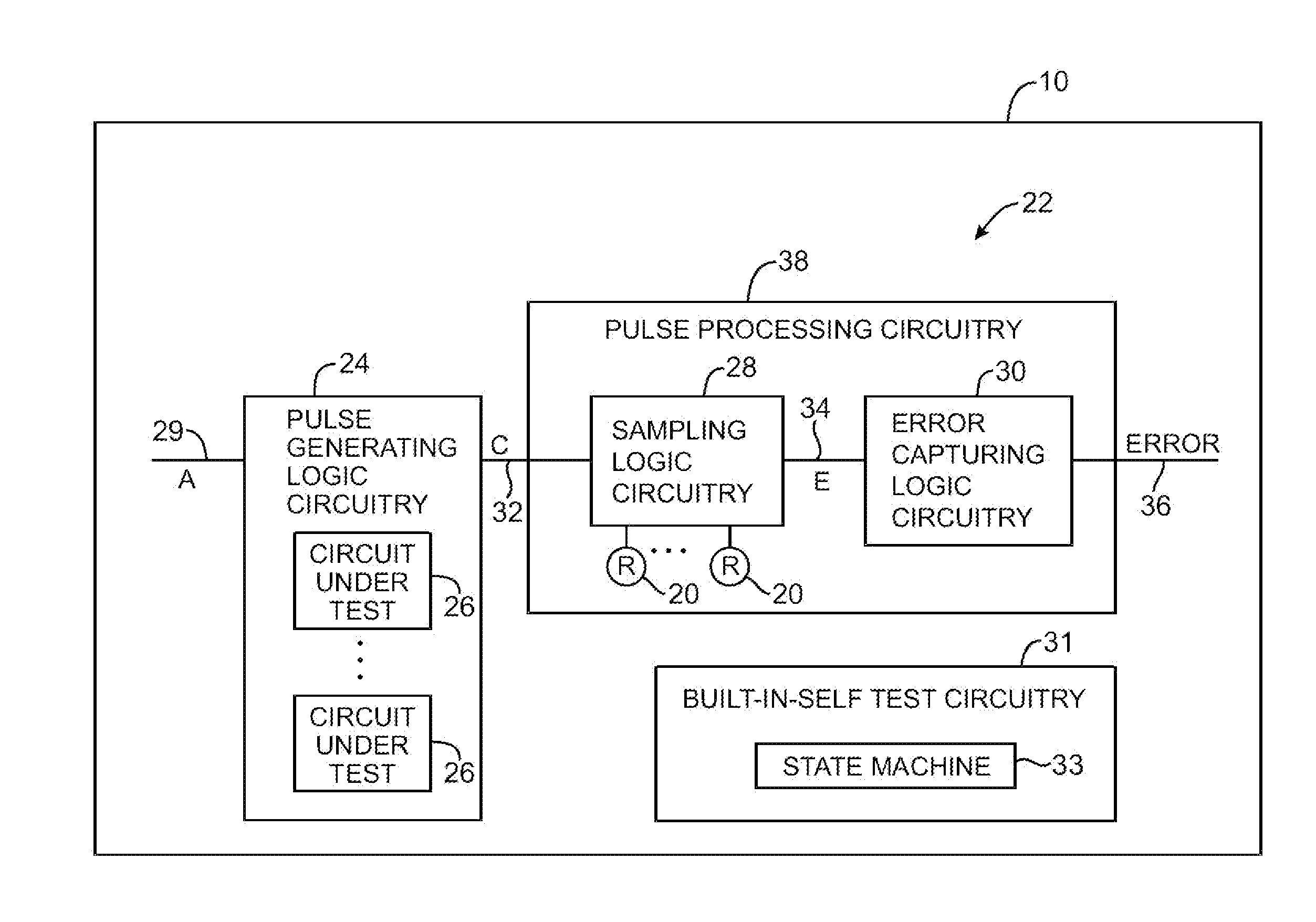
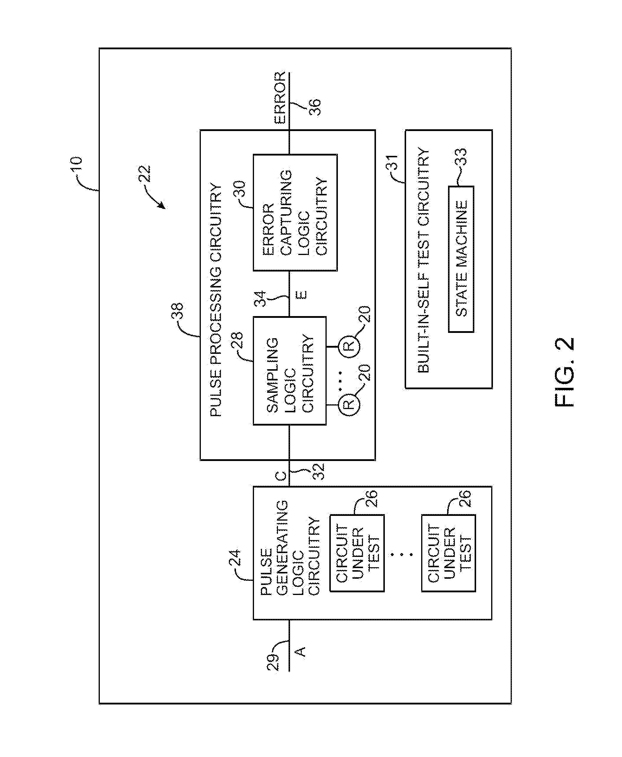
[0027]The present invention relates to delay test circuitry for testing a delay time associated with a circuit under test. The delay test circuitry may be incorporated into any suitable integrated circuit, such as a microprocessor, a digital signal processor, an application specific integrated circuit (ASIC), a memory chip, an audio or video integrated circuit, a communications circuit, etc. With one suitable arrangement, which is sometimes described herein as an example, the delay test circuitry may be located on an integrated circuit such as a programmable logic device.
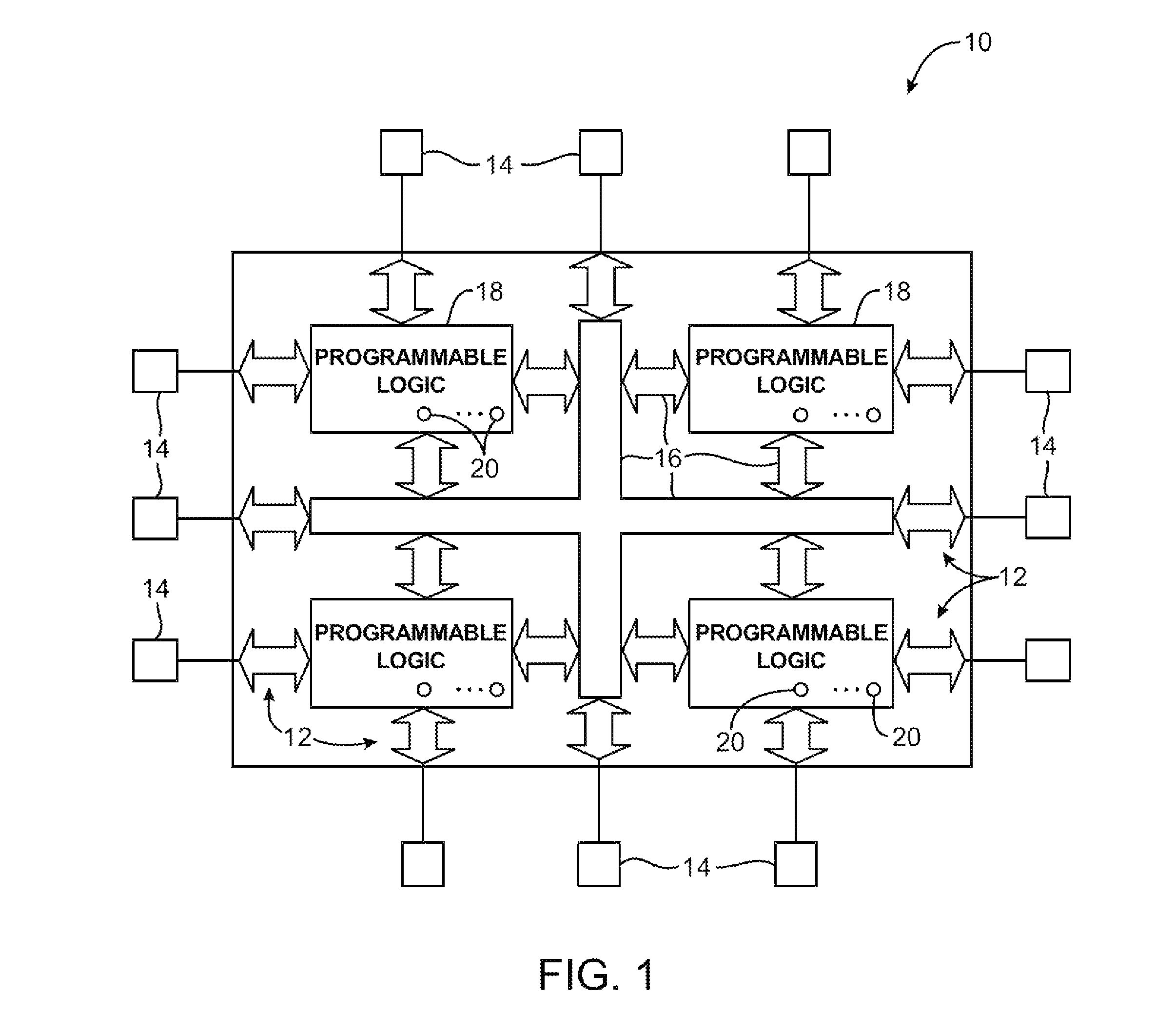
[0028]An illustrative programmable logic device 10 is shown in FIG. 1. Programmable logic device 10 has input-output circuitry 12 for driving signals off of device 10 and for receiving signals from other devices via input-output pins 14. Interconnection resources 16, also known as interconnects 16, such as global and local vertical and horizontal conductive lines and buses are used to route signals on device 10. Int...
PUM
 Abstract
Description
Claims
Application Information
 - R&D
- Intellectual Property
- Life Sciences
- Materials
- Tech Scout
- Unparalleled Data Quality
- Higher Quality Content
- 60% Fewer Hallucinations
Browse by: Latest US Patents, China's latest patents, Technical Efficacy Thesaurus, Application Domain, Technology Topic, Popular Technical Reports.
© 2025 PatSnap. All rights reserved.Legal|Privacy policy|Modern Slavery Act Transparency Statement|Sitemap|About US| Contact US: help@patsnap.com


