
Clock circuit with programmable load capacitors

a load capacitor and clock circuit technology, applied in the field of integrated circuits, can solve the problems of increasing component counts, consuming valuable board space, complex switching schemes, etc., and achieve the effect of reducing component counts and board siz

Inactive Publication Date: 2008-07-15
SILICON LAB INC
View PDF12 Cites 3 Cited by
  • Summary
  • Abstract
  • Description
  • Claims
  • Application Information

AI Technical Summary

Benefits of technology

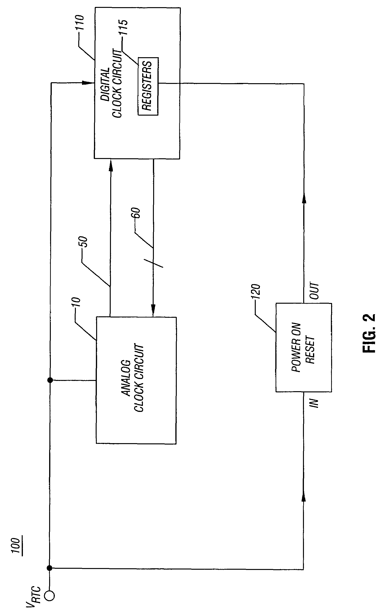
[0007]Other embodiments may be implemented in an IC and may include analog and digital circuitry to form a real time clock. The analog portion may have programmable load capacitors and the digital portion may be used to provide an initial control signal to the programmable load capacitors upon power up of the real time clock. In such manner, the real time clock can provide a clock signal to enable additional circuitry of the IC to be powered on. Once this additional circuitry is powered on, the load capacitors may then be provided with an operating control signal to enable a target reference clock frequency to be obtained. In some embodiments, the programmable load capacitors may be fabricated on the IC itself, reducing component counts and board size.

Problems solved by technology

Accordingly, load capacitors are typically implemented using off-chip capacitors, increasing component counts, as well as consuming valuable board area.
However, such switching schemes are complex and inefficient, and consume additional power.

Method used


Image

  • Clock circuit with programmable load capacitors
  • Clock circuit with programmable load capacitors
  • Clock circuit with programmable load capacitors

Examples


Embodiment Construction

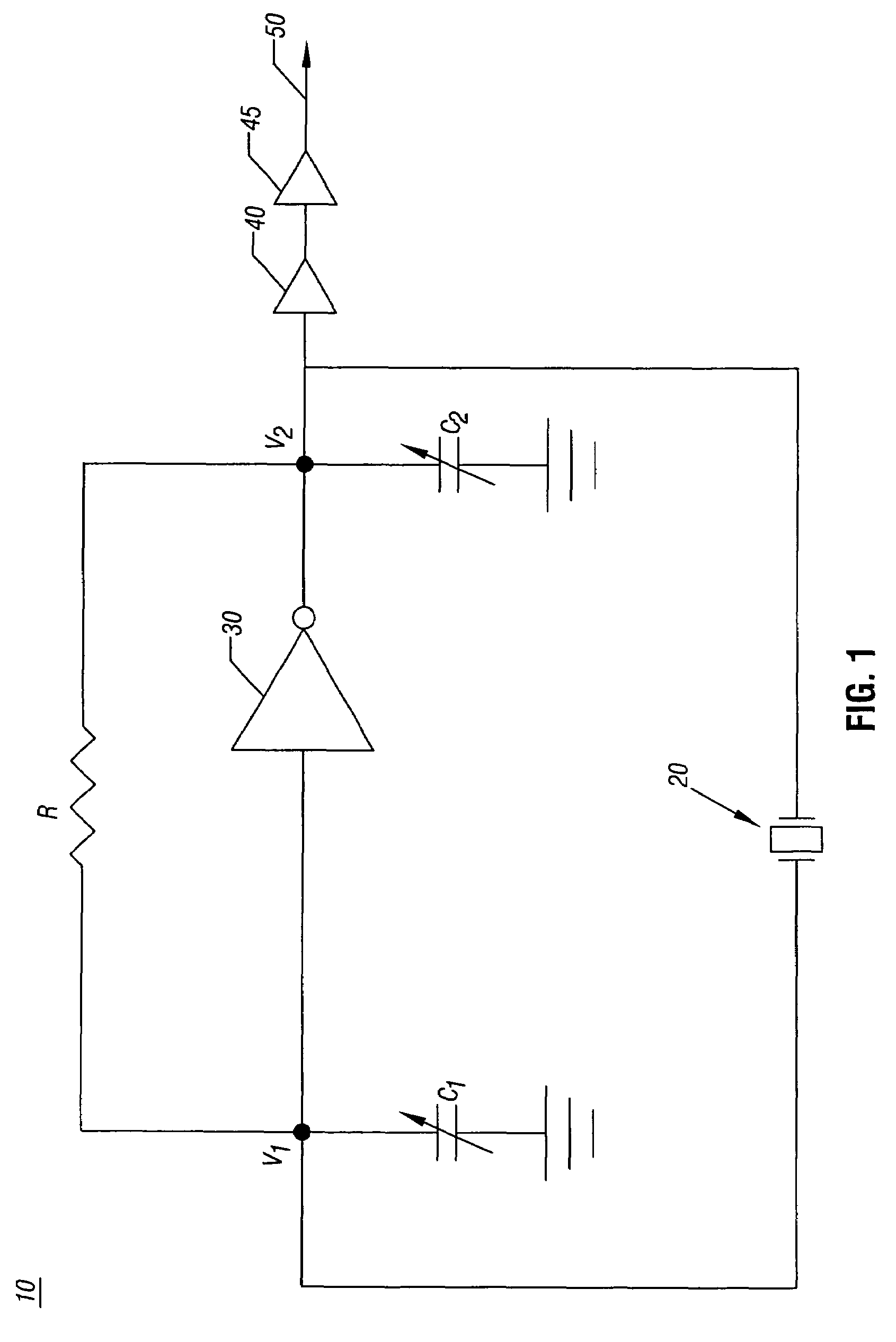
[0015]Referring now to FIG. 1, shown is a block diagram of a clock circuit 10 in accordance with one embodiment of the present invention. More specifically, clock circuit 10 is an analog portion of a real time clock (RTC) circuit. While described herein as a real time clock circuit, it is to be understood that the scope of the present invention is not so limited and that analog clock circuit 10 may take other forms. In various embodiments, analog clock circuit 10 may be implemented in an integrated circuit (IC) such that virtually all of the components of analog clock circuit 10 are on chip, thus reducing cost and board area.

[0016]As shown in FIG. 1, analog clock circuit 10 may take the form of a crystal oscillator, such as a Colpitts oscillator although other oscillator types are possible. Analog clock circuit 10 includes a crystal 20 which may be coupled at nodes V1 and V2 to load capacitors C1 and C2. In various embodiments, load capacitors C1 and C2 may be on-chip capacitors for...


PUM


Abstract

In one embodiment, the present invention includes methods and apparatus for providing initial control values to programmable load capacitors of an oscillator, such as that of a real time clock circuit. Using the initial values, the real time clock circuit may begin operation, enabling additional circuitry within an integrated circuit to begin operation. This additional circuitry may cause operating values to program the load capacitors to provide a desired reference clock based on a given system's requirements.

Description

FIELD OF THE INVENTION[0001]The present invention relates to integrated circuits (ICs), and more particularly to clock circuits.BACKGROUND[0002]Clock circuits are used in many analog ICs to provide reference clock signals. One particular type of clock circuit is a real time clock (RTC). An RTC is used to provide a reference clock, and can also be used to provide real time clock functions (i.e., date and time functions). An RTC typically includes an analog portion and a digital portion. The analog portion typically includes an oscillator and buffer circuitry, while the digital portion typically includes digital counters for implementing the real time functions.[0003]Typically, the oscillator of the analog portion of a real time clock is a crystal oscillator that uses load capacitors to generate a desired oscillation frequency. The value of the load capacitors may vary, depending on a crystal chosen for use in a system. Accordingly, load capacitors are typically implemented using off-...

Claims


Application Information

Patent Timeline
Patent Type & Authority Patents(United States)
IPC IPC(8): H03B5/12
CPCH03B5/36H03K3/0307H03K3/012H03B2201/0266
Inventor SHENG, WENJUNGSOMAYAJULA, SHYAM S.GONG, XUE-MEI
Owner SILICON LAB INC
Learn More