Eureka AIR delivers breakthrough ideas for toughest innovation challenges, trusted by R&D personnel around the world.

Direct conversion receiver having a low pass pole implemented with an active low pass filter

a low-pass filter and receiver technology, applied in the field of direct conversion rf receivers, can solve the problems of increasing fabrication/testing complexity, increasing cost, and inability to make large ohmic values of rb>1/b> and rb>3/b>, so as to reduce component count and cost, and increase reliability

Active Publication Date: 2006-06-13
HMD GLOBAL
View PDF6 Cites 44 Cited by
  • Summary
  • Abstract
  • Description
  • Claims
  • Application Information

AI Technical Summary

Benefits of technology

[0013]In a preferred embodiment at least the down-conversion mixer and the low pass filter are implemented as part of an integrated circuit, and the resistors and the capacitors are fabricated within the integrated circuit, thereby reducing component count and cost while increasing reliability.

Problems solved by technology

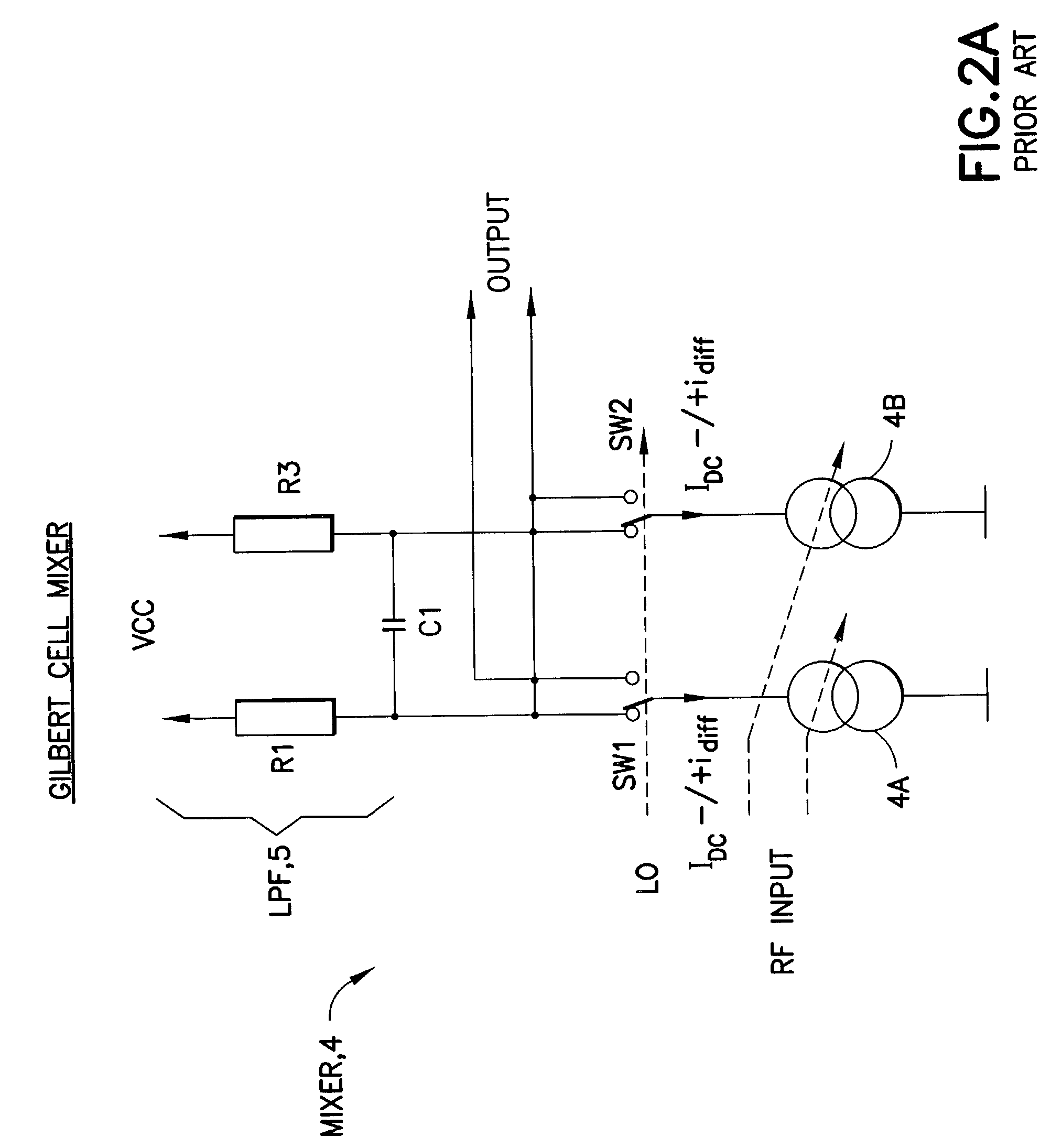
However, the ohmic value of R1 and R3 cannot be made large as an undesirable large DC voltage drop will result.
This solution, however, creates a problem when it is desired to fabricate the DCR in an integrated circuit form, as the required large value of capacitance for C1 correspondingly requires a substantial amount of integrated circuit area to implement.
An alternative solution is to make C1 an external discrete component, but this approach requires that additional integrated circuit pins be provided, and thus adds cost, increases fabrication / testing complexity, and introduces a possible interference source and imbalance due to pin-related parasitics.

Method used


Image

  • Direct conversion receiver having a low pass pole implemented with an active low pass filter
  • Direct conversion receiver having a low pass pole implemented with an active low pass filter
  • Direct conversion receiver having a low pass pole implemented with an active low pass filter

Examples


Embodiment Construction

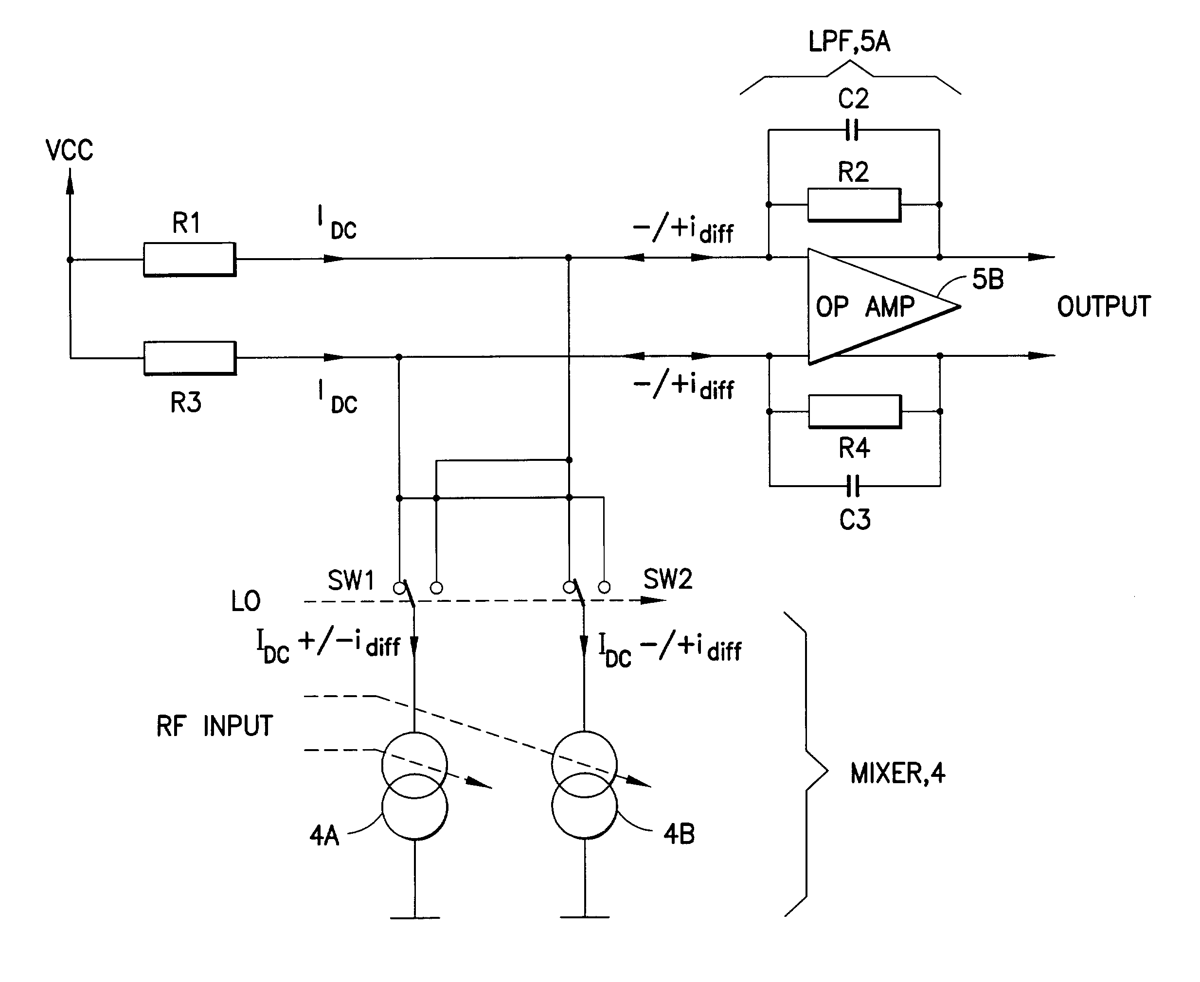
[0024]Reference is now made to FIG. 3 for showing a simplified schematic diagram of an embodiment of the mixer 5 and an improved low pass filter 5A in accordance with the teachings of this invention. The output currents from the mixer core 4 are connected to the virtual ground node of the operational amplifier (op amp)5B. Because of feedback both inputs to the op amp 5B are at the same DC potential, and differential currents are forced to go through the feedback circuitry. However, common mode DC currents can also be supplied by R1 and R3. This is preferred, as it means that the comer frequency of the low pass pole is not affected by the values of R1 and R3. As such, their values can be made small, thereby producing a low DC voltage drop from the supply voltage VCC.

[0025]In this embodiment the low pass pole of the LPF is implemented not by the passive LP filter comprised of R1, R3 and C1, but instead by an active LP filter comprised of the operational amplifier 5B in combination wit...


PUM


Abstract

A wireless communications mobile station (10) includes at least one antenna (240) and a RF transceiver (210,220) containing a direct conversion receiver (1) coupled to the antenna. The direct conversion receiver contains a low noise amplifier (3) for amplifying a received RF signal and for outputting the amplified RF signal to a current switching down-conversion mixer (4). The down-conversion mixer has a first input node for receiving the amplified RF signal, a second input node for receiving a local oscillator (LO) signal for mixing with the amplified RF signal and an output node coupled to an input of an operational amplifier forming a low pass filter (5A). In accordance with an aspect of this invention the low pass filter has a low pass pole generated by a resistor R and a capacitor C coupled in parallel in a feedback path of the operational amplifier, where a low pass comer frequency of the low pass filter is inversely proportional to the product of R and C. In a preferred embodiment at least the down-conversion mixer and the low pass filter are implemented as part of an integrated circuit, and the resistor and the capacitor are fabricated within the integrated circuit.

Description

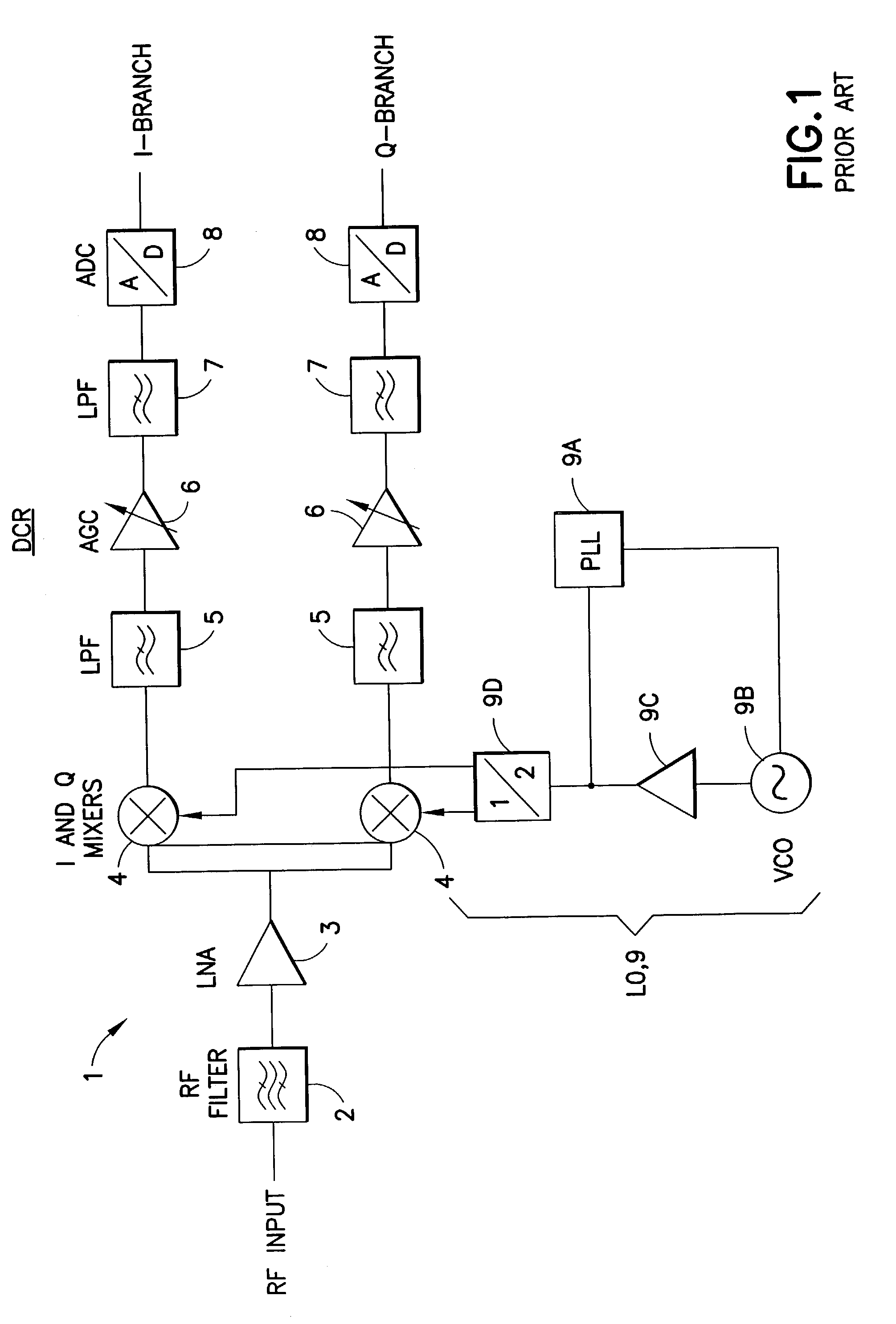
TECHNICAL FIELD[0001]The teachings of this invention relate generally to radio frequency (RF) receivers and, more specifically, relate to direct conversion RF receivers and to mixers used with direct conversion RF receivers.BACKGROUND[0002]Direct conversion RF receivers, or more simply direct conversion receivers (DCRs), have been found to be attractive for use in mass produced consumer communication products such as cellular telephones and personal communicators. This is due to the fact that the DCR has a relatively simple structure (as compared to the conventional heterodyne or superheterodyne type of receiver), a reduced component count, and enables a high level of circuit integration to be achieved. The DCR is so-named because the received RF frequency is down-mixed or down-converted directly to a DC baseband signal, or to a very low frequency baseband signal, without undergoing one or more stages of intermediate frequency (IF) down-mixing.[0003]FIG. 1 is a simplified schematic ...

Claims


Application Information

Patent Timeline
IPC IPC(8): H04B1/26H04B1/30
CPCH04B1/30
Inventor KUIRI, TAPIO
Owner HMD GLOBAL
Why Eureka
Eureka Blog
Learn More