
Lateral acoustic wave resonator comprising a suspended membrane of low damping resonator material

a resonator material and suspension membrane technology, applied in piezoelectric/electrostrictive/magnetostrictive devices, piezoelectric/electrostriction/magnetostriction machines, electrical instruments, etc., can solve the problems of limiting the performance of zno based resonator designs, limiting the application of high material damping, and limiting the phonon-phonon damping limit. , the effect of minimizing the influence o

Active Publication Date: 2013-09-03
NAT TECH & ENG SOLUTIONS OF SANDIA LLC
View PDF7 Cites 42 Cited by
  • Summary
  • Abstract
  • Description
  • Claims
  • Application Information

AI Technical Summary

Benefits of technology

This patent is about a new type of resonator that uses sound waves to filter out specific frequencies. It consists of a thin membrane made of silicon carbide, which has very low damping, and a piezoelectric transducer that generates sound waves. These sound waves create a standing wave resonance in the membrane, which can be used to filter out unwanted frequencies. The membrane can also have a special design that allows for the resonator to be integrated with other components using advanced manufacturing processes. The resonator is scalable and can be easily integrated with existing technologies. Overall, this invention allows for better filtering of sound waves and is useful in a variety of applications.

Problems solved by technology

Dielectric losses at frequencies in excess of 1 GHz have been shown to limit the performance of ZnO based resonator designs.
Ceramics, such as PZT, exhibit slightly higher coupling coefficients; however, high material damping limits their application, particularly at high frequencies.
The resonant frequency of these devices is very sensitive to the film thickness, which in today's best atomic layer deposition systems is still limited to the range of 0.1%, translating to 1-nm uniformity in a 1-μm thick film.
Therefore, the resonant frequency and bandwidth of thickness-mode resonators are difficult to control.

Method used


Image

  • Lateral acoustic wave resonator comprising a suspended membrane of low damping resonator material
  • Lateral acoustic wave resonator comprising a suspended membrane of low damping resonator material
  • Lateral acoustic wave resonator comprising a suspended membrane of low damping resonator material

Examples


Embodiment Construction

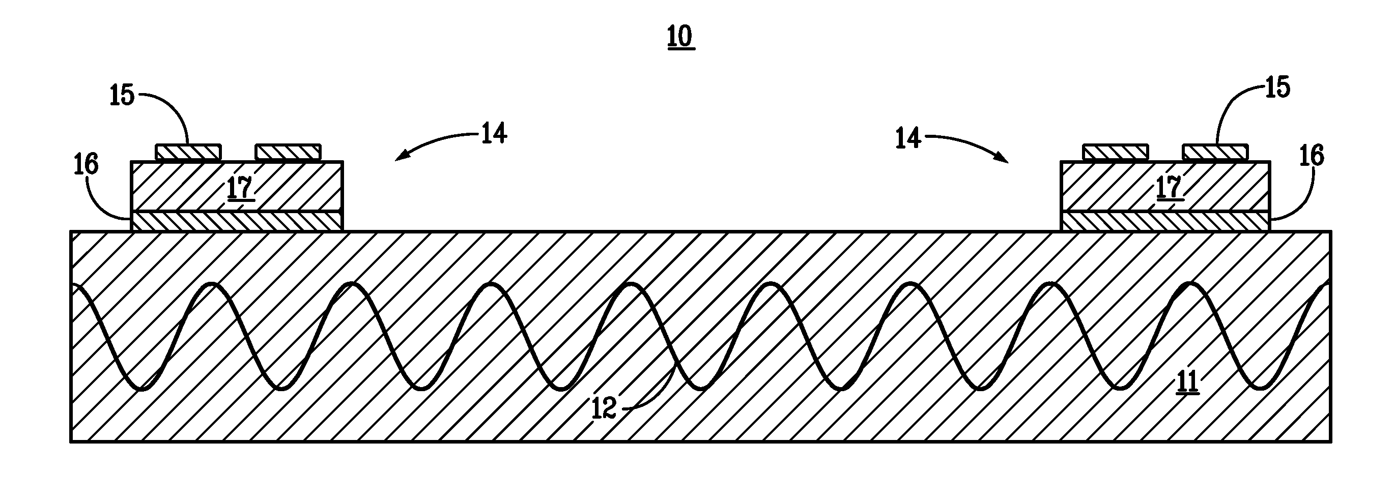
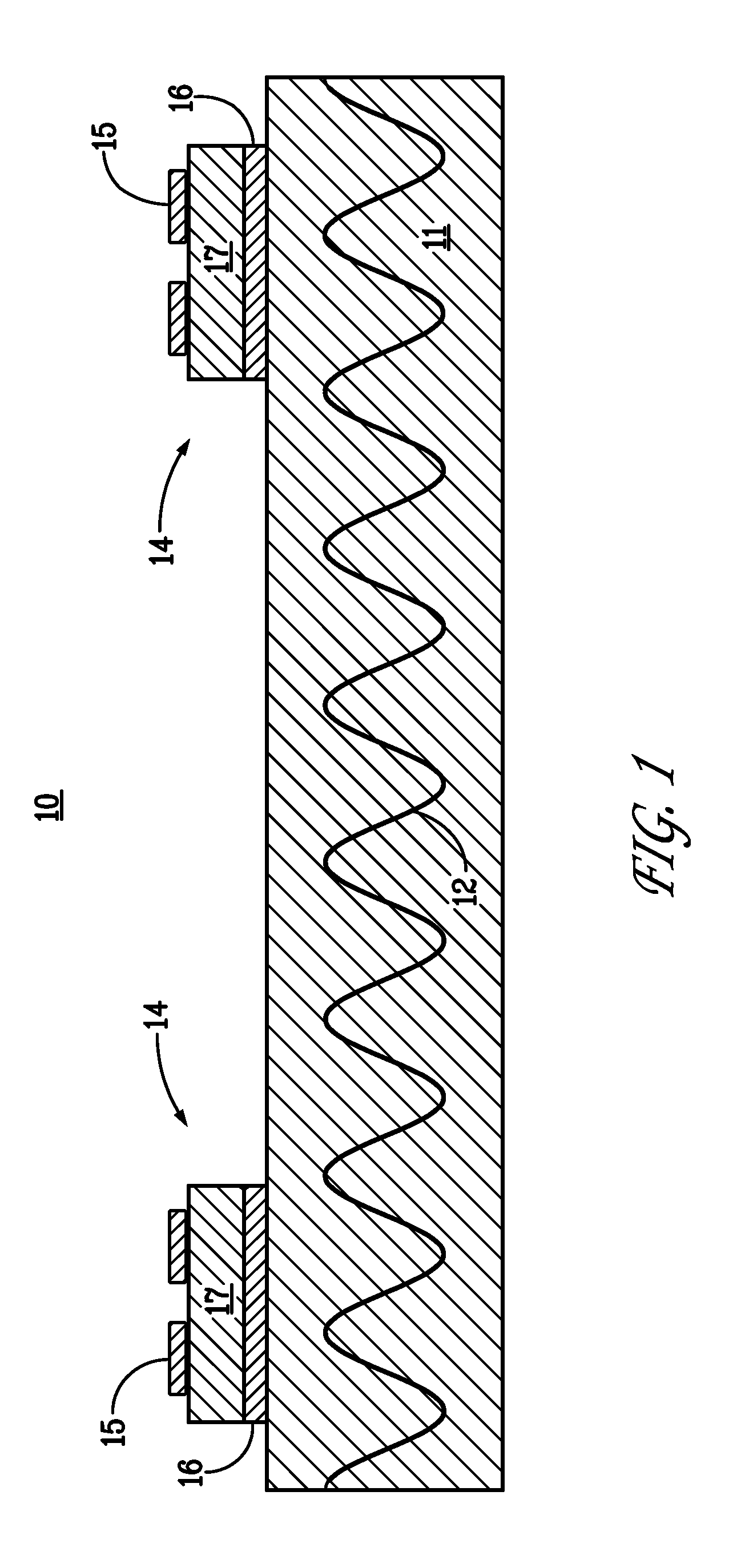
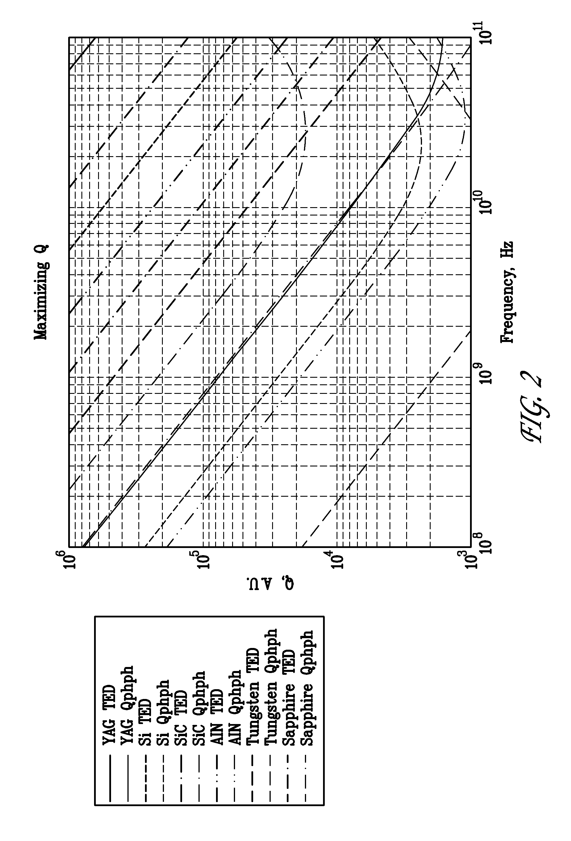
[0030]A very high-Q, low insertion loss resonator can be achieved by storing many overtone cycles of a lateral acoustic wave (i.e., Lamb wave) in a lithographically defined suspended membrane comprising a low damping resonator material. A similar overtone resonator approach for increasing Q has been reported for thickness-mode BAW resonators. See G. R. Kline et al.; and D. S. Bailey et al., “Frequency stability of high overtone bulk acoustic resonators,”IEEE Ultrasonics Sym., 509 (1990). The low damping resonator material can comprise a non-piezoelectric material, such as silicon carbide, sapphire, yttrium aluminum garnet, or diamond. The lateral overtone acoustic wave resonator can be electrically transduced by AIN piezoelectric couplers which have previously demonstrated low impedance transduction. See R. H. Olsson III et al., IEEE Freq. Cntl. Sym., 412 (2007). Similarly, other high-quality piezoelectric transducers, such as lead zirconate titanate, lithium niobate, zinc oxide, or...


PUM


Abstract

A very high-Q, low insertion loss resonator can be achieved by storing many overtone cycles of a lateral acoustic wave (i.e., Lamb wave) in a lithographically defined suspended membrane comprising a low damping resonator material, such as silicon carbide. The high-Q resonator can sets up a Fabry-Perot cavity in a low-damping resonator material using high-reflectivity acoustic end mirrors, which can comprise phononic crystals. The lateral overtone acoustic wave resonator can be electrically transduced by piezoelectric couplers. The resonator Q can be increased without increasing the impedance or insertion loss by storing many cycles or wavelengths in the high-Q resonator material, with much lower damping than the piezoelectric transducer material.

Description

STATEMENT OF GOVERNMENT INTEREST[0001]This invention was made with Government support under contract no. DE-AC04-94AL85000 awarded by the U.S. Department of Energy to Sandia Corporation. The Government has certain rights in the invention.FIELD OF THE INVENTION[0002]The present invention relates to radiofrequency resonators and, in particular, to a lateral acoustic wave resonator that can achieve a high quality factor.BACKGROUND OF THE INVENTION[0003]Highly selective radiofrequency (RF) filters are used in a variety of applications to avoid interference between adjacent bands, including TV broadcasting, GPS systems, mobile phone systems, and wireless local area networks. For example, mobile phones need RF filters to protect the sensitive receive path from interference by transmit signals from other users and noise from various RF sources. Bandpass RF filters operate in the 100 MHz to 10 GHz frequency range and preferably have extremely low losses and high quality factors (Q). In part...

Claims


Application Information

Patent Timeline
Patent Type & Authority Patents(United States)
IPC IPC(8): H03H9/54
CPCH03H9/02228
Inventor OLSSON, ROY H.EL-KADY, IHAB F.ZIAEI-MOAYYED, MARYAMBRANCH, DARREN W.SU, MEHMET F.REINKE, CHARLES M.
Owner NAT TECH & ENG SOLUTIONS OF SANDIA LLC
Learn More