
Chemical decontamination apparatus and decontamination method therein

a chemical decontamination and decontamination apparatus technology, applied in lighting and heating apparatus, nuclear engineering, liquid cleaning, etc., can solve the problems of weak oxidizing power of ozone aqueous solution, small oxidation power, and inability to suppress the corrosion of the structural materials of the reactor by ozone water, so as to achieve efficient and effective suppression of corrosion of decontamination objects, enhanced decontamination performance, and enhanced cleaning

Inactive Publication Date: 2013-05-14
KK TOSHIBA
View PDF23 Cites 0 Cited by
  • Summary
  • Abstract
  • Description
  • Claims
  • Application Information

AI Technical Summary

Benefits of technology

The approach effectively decomposes oxide films, suppresses corrosion of reactor structural materials, and maintains decontamination performance while reducing secondary waste production and operational complexity, ensuring efficient and stable ozone distribution within the reactor system.

Problems solved by technology

However, because the oxidation auxiliary agent added to water is nitric acid, the oxidizing power of the ozone aqueous solution is weak, and corrosion of the reactor structural materials by ozone water cannot be suppressed, which is problematic.
However, because phosphoric acid is close to a weak acid, addition of phosphoric acid as the oxidation auxiliary agent yields only small oxidation power and cannot efficiently and effectively suppress corrosion of the reactor structural materials.
As a result, large quantities of secondary wastes are produced after decontamination and a new problem arises in that disposal of the secondary wastes requires much labor and cost.
The chemical decontamination technique that uses a multitubular hollow fiber membrane mixer described in Patent Document 3 has a drawback.
That is, because the multitubular hollow fiber membrane mixer is made of a resin, it is easily damaged.
In the case where the decontamination object has a large scale, such as in the case of internal decontamination of the reactor primary system, ozone's self-decomposability may lead to a decrease in ozone concentration during circulation and insufficient decontamination effects.
Since the decontamination water is a gas-liquid mixed flow of water and ozone, ozone injection to the pump upstream side of the reactor recirculation pump may cause pump cavitation in the pump unit of the recirculation pump and may thereby damage the pump.
As in the gas-dissolving apparatus described in Patent Document 5, application of a technique that uses an ejector to incore chemical decontamination apparatuses for reactors and decontamination methods therefor causes delay of work for installing an ejector in the reactor or an interference problem with the reactor structures.
Thus, implementation of this technique is difficult.
However, in the case of internal decontamination of the reactor primary system, the overall system volume is large.
Thus, the concentration of ozone must be high, and it is difficult to securely obtain and maintain a sufficient ozone concentration.
Furthermore, a technique of diffusing ozone in the downstream flow is also available as described in Patent Document 6, but it is difficult to apply this ozone diffusion method to the incore chemical decontamination apparatus for a reactor.
Hence, the apparatus becomes complicated.

Method used


Image

  • Chemical decontamination apparatus and decontamination method therein
  • Chemical decontamination apparatus and decontamination method therein
  • Chemical decontamination apparatus and decontamination method therein

Examples


first embodiment

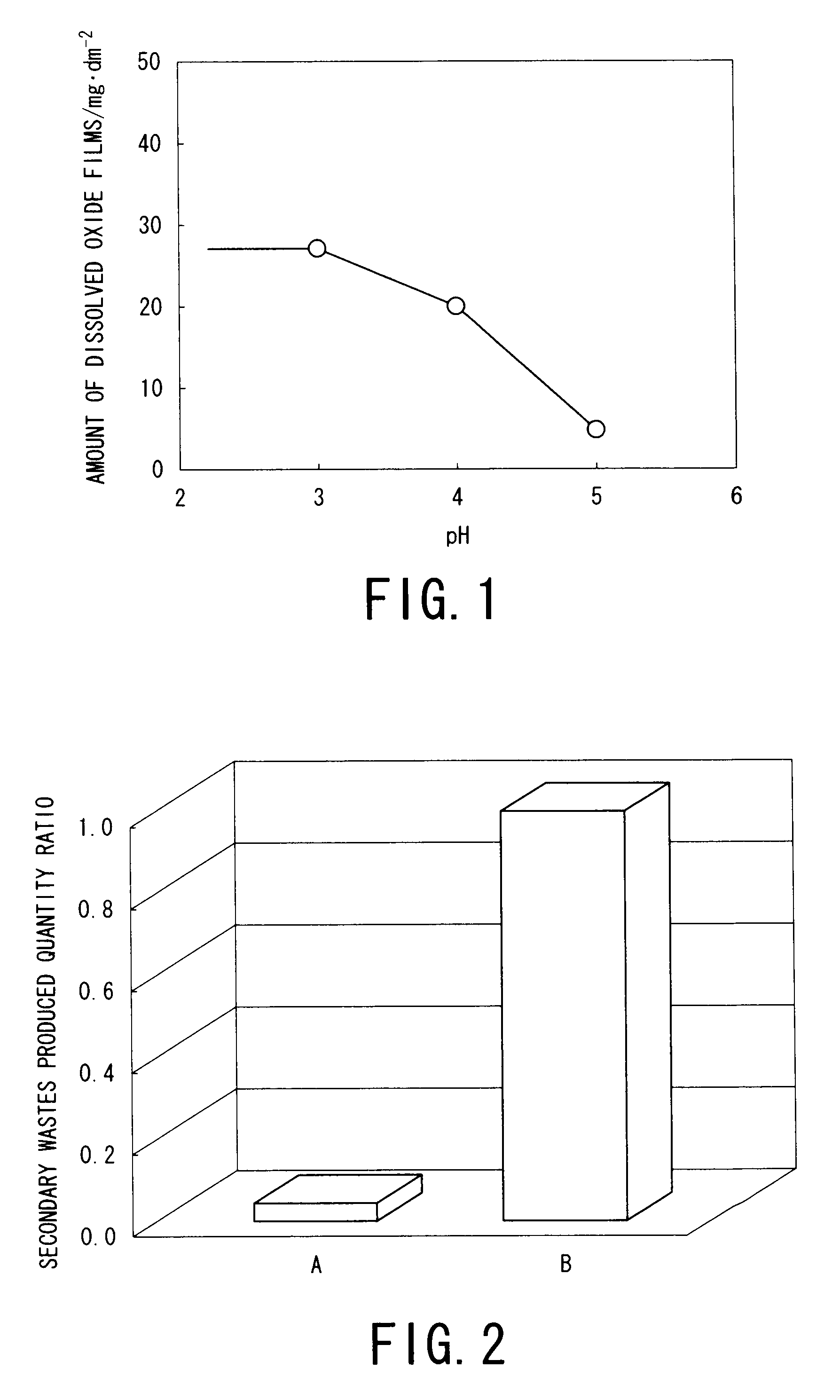
[0079]A chemical decontamination method according to a first embodiment of the present invention is, for example, suitable for decontamination of the reactor structural materials and suppression of corrosion, for example.

[0080]In this decontamination method, a nickel-based alloy, for example, Inconel 182, was chosen as the reactor structural material. An Inconel test piece was immersed in ozone water to conduct test confirming whether corrosion occurred or not.

[0081]The size of the Inconel 182 test piece as the decontamination object was, for example, 30×10×2 mm3, and the immersion conditions of the test piece were as follows: dissolve ozone concentration in ozone water: 3 ppm, temperature: 80° C., immersion time 10 h.

[0082]The following test parameters were used to conduct the test for confirming whether corrosion of the Inconel test piece occurred or not:

[0083]i) no oxidation auxiliary agent or pH adjustor was added;

[0084]ii) 20 ppm of phosphoric acid was added as the oxidation au...

second embodiment

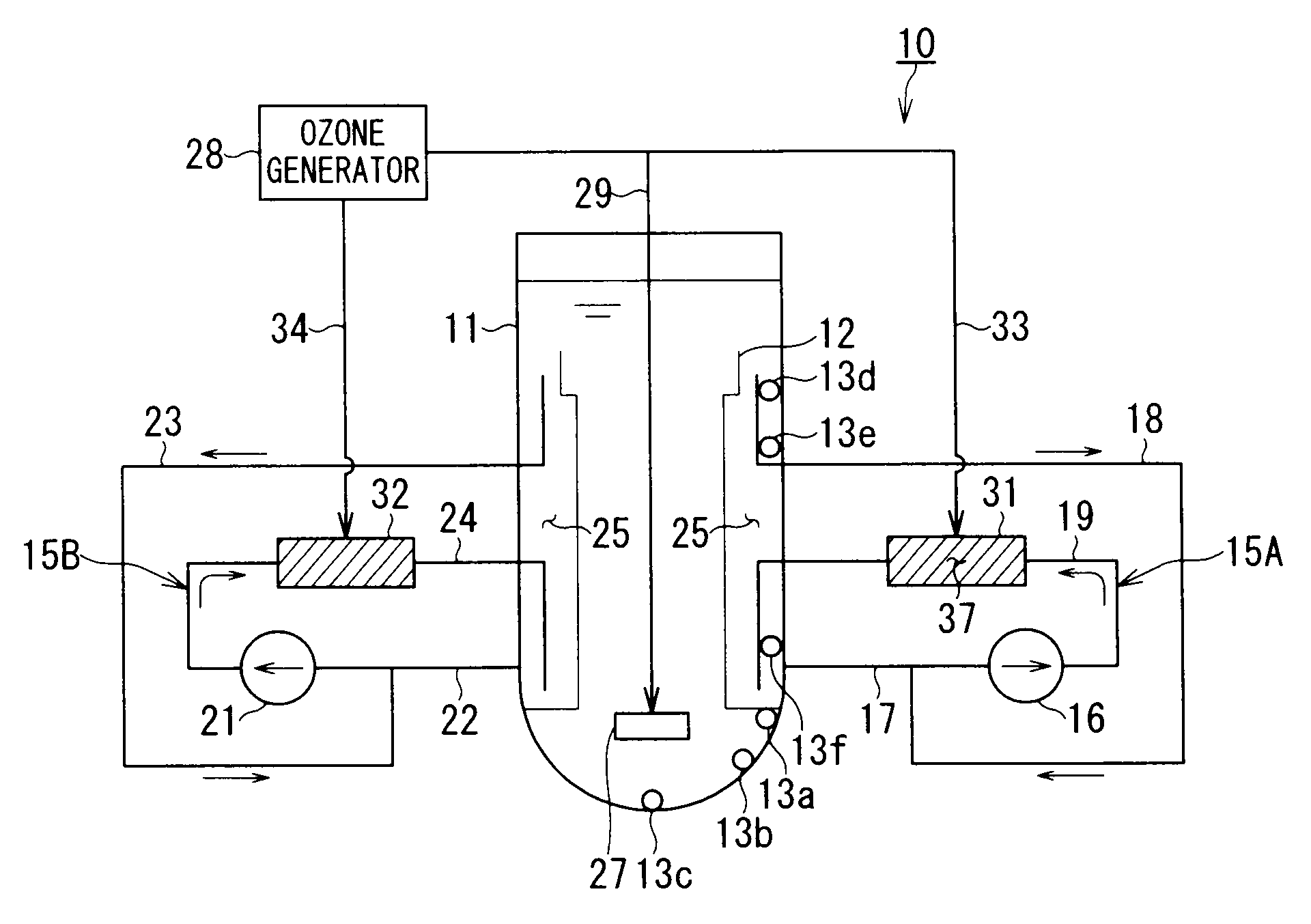
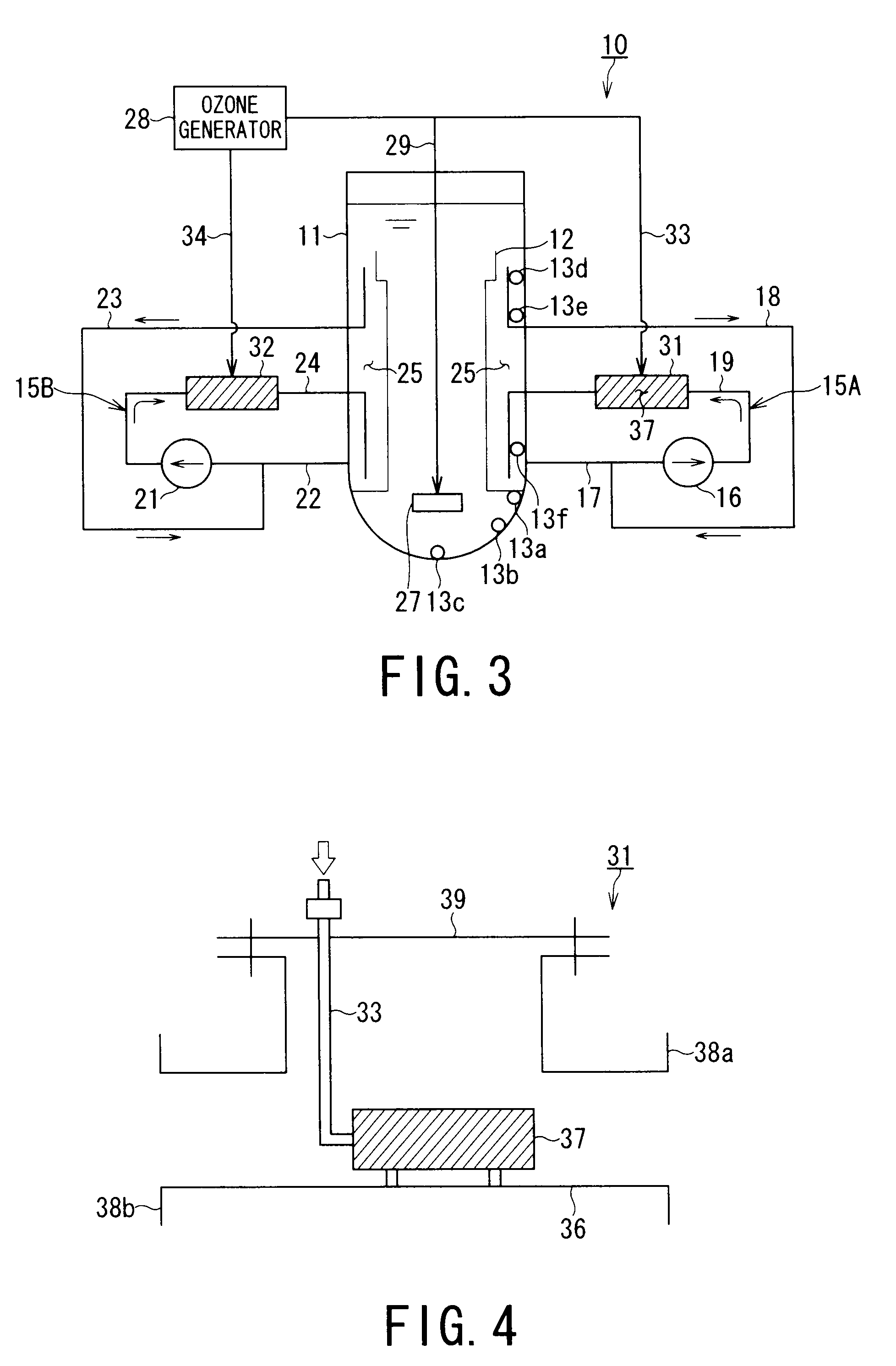
[0102]FIG. 3 is a schematic diagram showing a chemical decontamination apparatus according to a second embodiment of the present invention.

[0103]FIG. 3 shows a dissolved ozone detecting test system simulating BWR to which the chemical decontamination apparatus of the present invention is applied. A dissolved ozone detecting test system 10 includes a cylindrical tank 11 simulating a reactor pressure vessel, and a substantially cylindrical or sleeve-shaped internal structure 12 for controlling the water flow in the tank 11. The internal structure 12 simulates a core shroud. The capacity of the cylindrical tank 11 is, for example, 3.5 m3. In this example, the cylindrical tank 11 and the internal structure 12 correspond to the decontamination objects.

[0104]Sampling nozzles 13a to 13f for measuring the dissolved ozone concentration in water in the cylindrical tank 11 are installed at a plurality of places, e.g., six places, on the inner peripheral wall of the cylindrical tank 11. Water i...

third embodiment

[0134]FIG. 7 is a schematic diagram showing a chemical decontamination apparatus according to a third embodiment of the present invention.

[0135]This embodiment shows a chemical decontamination apparatus 51 that decontaminates a reactor pressure vessel 50 of a boiling water reactor (BWR) with ozone.

[0136]A reactor core 53 is disposed inside the reactor pressure vessel 50, and many fuel assemblies are supported by a core supporting plate 54 and an upper grid 55 inside the reactor core 53. Control rods (not shown) are charged in and discharged from the reactor core 53 by a control rod driving mechanism 56. FIG. 7 shows a state in which reactor equipments such as fuel assemblies, the control rods, a steam separator, a steam drier, and the like are removed.

[0137]The reactor core 53 is surrounded by a core shroud 57, and jet pumps 59 are disposed in a downcomer portion 58, which is an annular space between the core shroud 57 and the reactor pressure vessel 50. A plurality of jet pumps 59 ...


PUM

PropertyMeasurementUnit
pHaaaaaaaaaa
temperatureaaaaaaaaaa
pHaaaaaaaaaa

Abstract

A chemical decontamination apparatus of the present invention chemically dissolves radioactive substance-containing oxide films formed or adhering on the surface of a decontamination object by using ozone water to conduct decontamination. The chemical decontamination apparatus includes an ozone generating unit for generating ozone gas, an ozone supplying device for supplying the generated ozone gas to an ozone supplying unit in water, and a sintered metal element 37 which is disposed in the ozone supplying unit and to which ozone gas is supplied from the ozone supplying device. The ozone gas supplied to a sintered metal element interior from the ozone supplying device is allowed to flow out of the element into water so as to generate ozone water.

Description

CROSS REFERENCE TO RELATED APPLICATION[0001]This application is a 371 of PCT / JP07 / 052,028, filed on Feb. 6, 2007, and claims priority to the following Japanese Patent Applications: JP 2006-032575 filed on Feb. 9, 2006, and JP 2006-053698, filed on Feb. 28, 2006.TECHNICAL FIELD[0002]The present invention relates to a chemical decontamination technique using ozone. In particular, it relates to a chemical decontamination apparatus that performs decontamination by chemically dissolving oxide films adhering or formed on surfaces of decontamination objects, e.g., reactor structural materials in a reactor primary system, such as reactor equipment, piping, and the like, and also relates to a chemical decontamination decontamination method.Background Art[0003]Many patent applications related to chemical decontamination techniques that use ozone have been filed. Chemical decontamination techniques are being employed in chemical decontamination operation of actual reactors.[0004]Patent Documen...

Claims


Application Information

Patent Timeline
Patent Type & Authority Patents(United States)
IPC IPC(8): G21F9/00B08B7/00B08B3/00B08B9/00C03C23/00B01J19/08
CPCG21F9/002G21F9/28G21F9/004B08B3/04
Inventor ENDA, MASAMIICHIKAWA, NAGAYOSHIKANEDA, MASAYUKIKANASAKI, TAKESHIYOSHII, TOSHIHIROYAITA, YUMIINAMI, ICHIRO
Owner KK TOSHIBA
Learn More