
Pouring insert

a technology of inserts and liquids, applied in the field of inserts, can solve the problems of unwelcome waiting time, unwelcome changes in wine temperature, unsatisfactory effect, and unsatisfactory effect of liquid-air interface, and achieve the effect of maximizing the liquid-air interfa

Inactive Publication Date: 2013-04-09
IDEAS DENMARK
View PDF19 Cites 16 Cited by
  • Summary
  • Abstract
  • Description
  • Claims
  • Application Information

AI Technical Summary

Benefits of technology

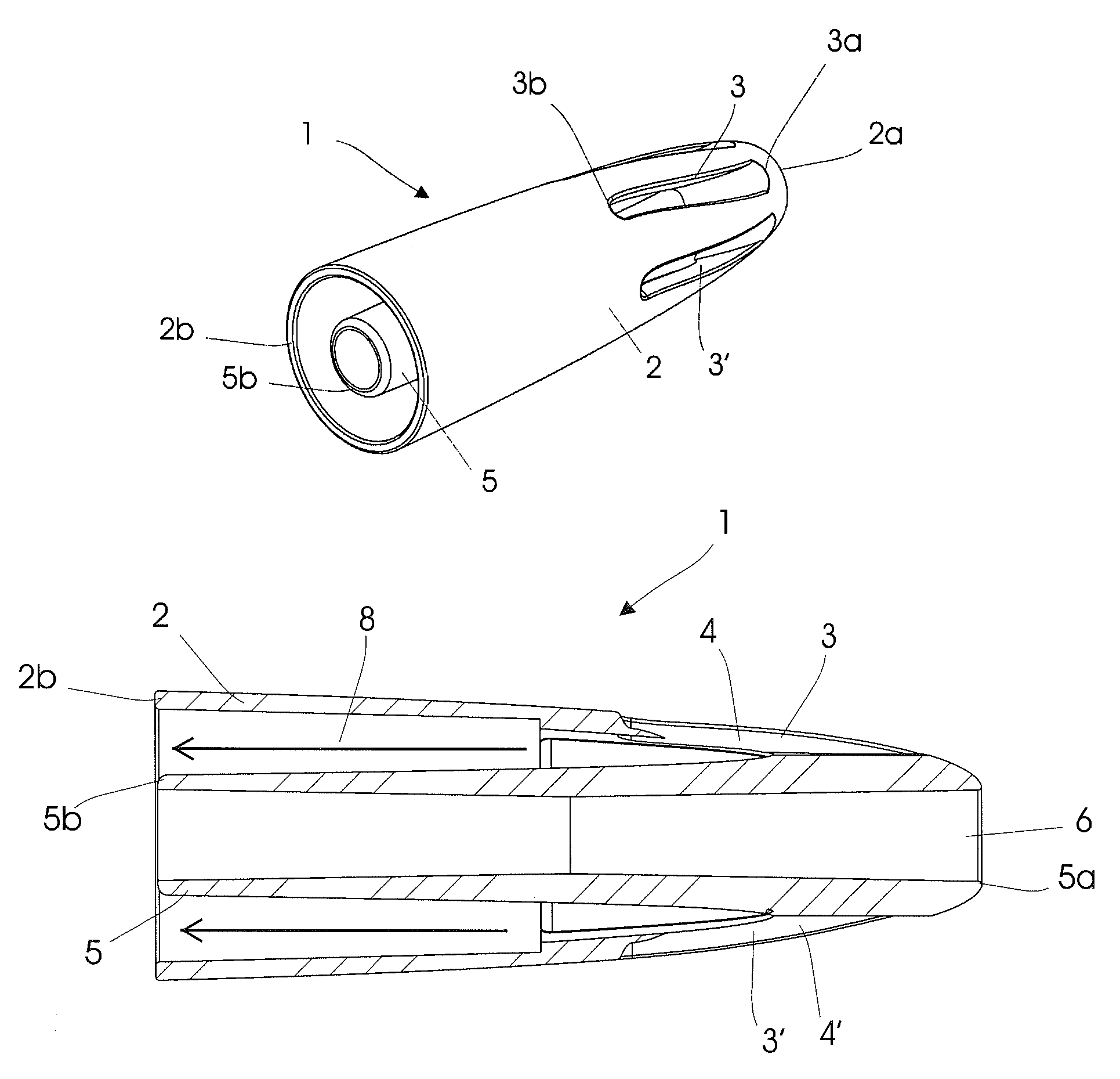
[0009]Thus, it is a first aspect of the present invention to provide a pouring insert which maximizes the liquid-air interface while pouring liquid from a bottle.
[0010]It is a second aspect of the present invention to provide a pouring insert which is simple, cost-effective, and may be used with a variety of different container outlets.
[0012]It is a fourth aspect of the present invention to provide a pouring insert which contributes to a significant improvement of the aroma of wine poured through the insert.

Problems solved by technology

Tannins are plant polyphenols occurring in the skin and seeds of grapes, and often conveying a bitter, undesired taste.
This, however, often results in poor aeration due to the inherent rate limitation of air diffusion into stagnant liquid.
In addition, this technique may entail undesired changes in wine temperature as well as unwelcome waiting time.
A drawback of this approach is the obvious need of an additional container.
Again, this type of arrangement does little for maximising the interface between wine and air.
However, the air-liquid interface is only slightly increased compared to the above approaches since the apertures simply split the liquid flow into a number of smaller flows, but do not introduce any additional means for achieving turbulence and mixing.
The obvious disadvantages of this technique are energy consumption, increased expense and space requirements.

Method used


Image

  • Pouring insert
  • Pouring insert
  • Pouring insert

Examples


Embodiment Construction

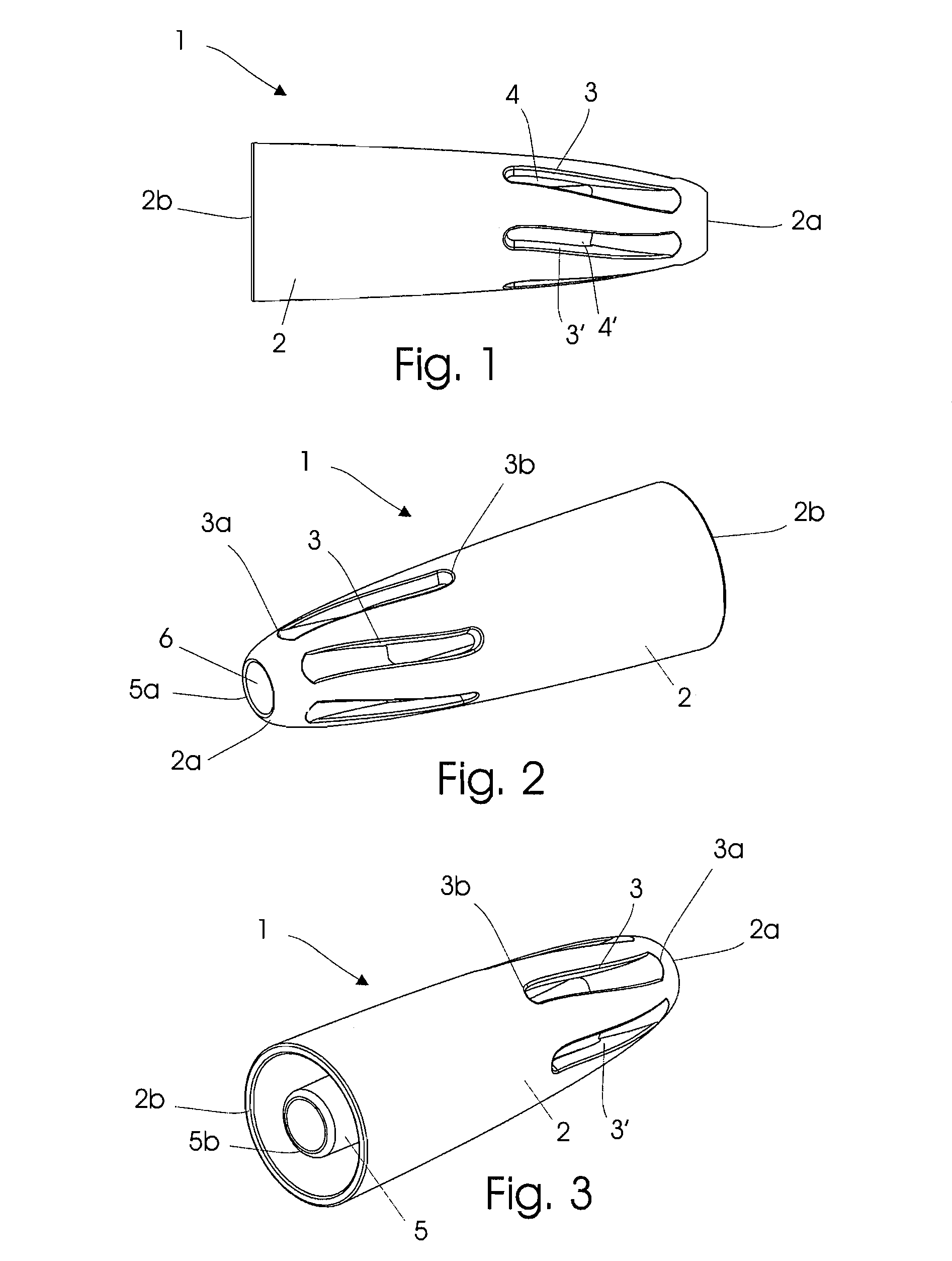
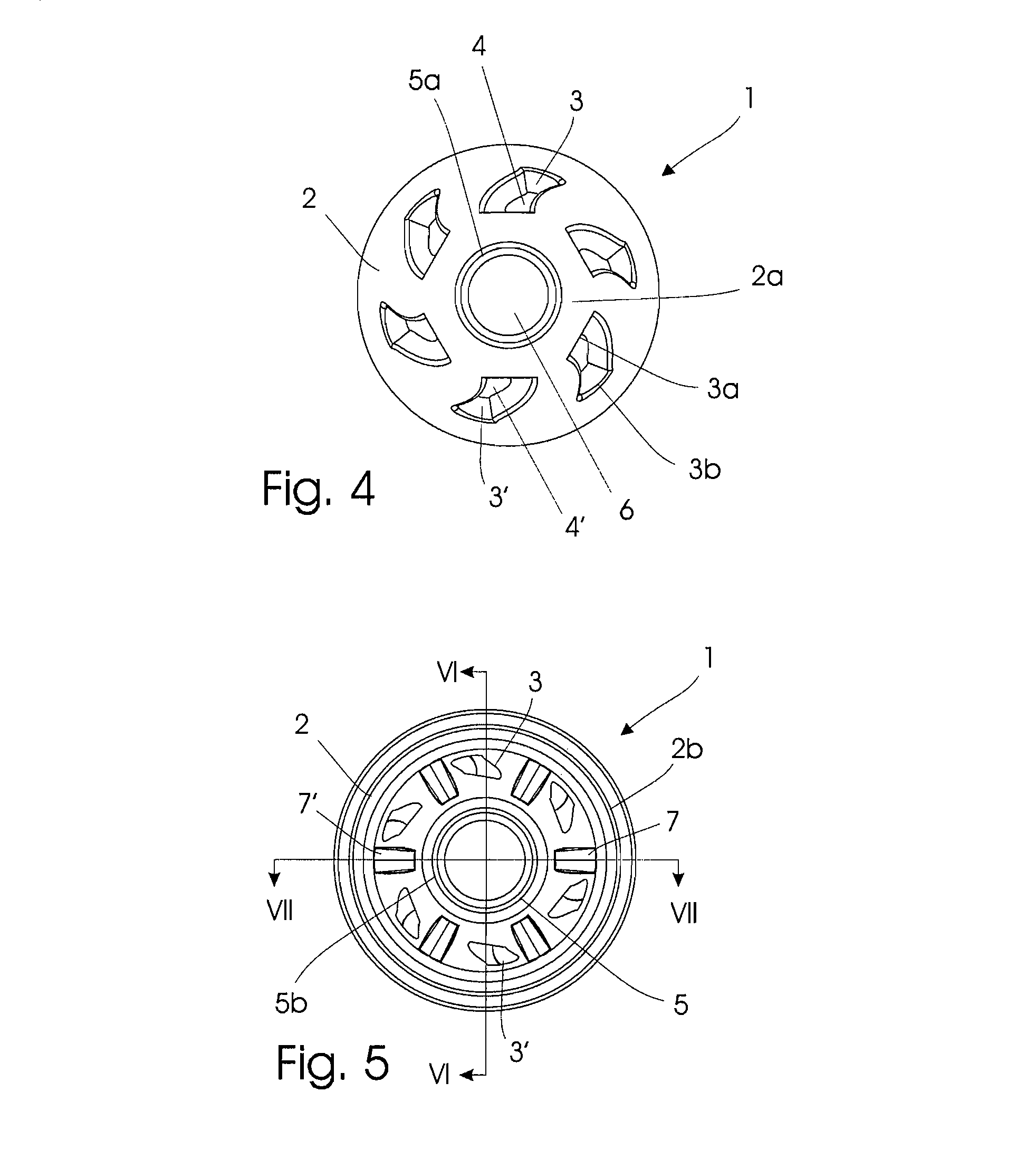
[0028]The terms “distal” and “proximal” as used herein refer to the location of elements relative to the user, who inserts the pouring insert into a liquid container outlet, for example a bottleneck of a wine bottle. The distal jacket end will therefore be located closer to the bottle's base whereas the proximal jacket end will be located further up the bottleneck and more distant from the bottle's base. The jacket may be pipe-shaped, which should be understood as comprising a cylindrical shape as well as pipe-shapes that have a quadrangular, oval or any otherwise shaped cross section.

[0029]The pouring insert may be inserted into a bottleneck with the distal ends of the jacket and the pipe entering the bottleneck first. When inserted, the longitudinal axis of the pouring insert will usually be aligned with the longitudinal axis of the bottleneck.

[0030]The jacket advantageously tapers towards its distal jacket end, thereby ensuring that the insert will fit several sizes of bottleneck...


PUM

PropertyMeasurementUnit
diameteraaaaaaaaaa
diameteraaaaaaaaaa
timeaaaaaaaaaa

Abstract

A pouring insert is provided for insertion into a container outlet, for example a bottleneck, for aerating liquids pored from the container. This is achieved by a combination of a hollow, tapering jacket with a hollow pipe axially disposed within it. The jacket features a plurality of elongated slots penetrating the jacket and allowing for liquid / air flow therethrough. The invention furthermore relates to a bottle pourer having a spout and the pouring insert described herein. The invention also relates to the use of the pouring insert and of the bottle pourer for aerating wine. Finally, the present invention relates to a method of manufacturing the pouring insert by injection molding.

Description

TECHNICAL FIELD[0001]The present invention relates to a pouring insert for insertion into a container outlet, for example a bottleneck, for aerating liquids pored from the container. The invention furthermore relates to a bottle pourer with a spout, the bottle pourer comprising the pouring insert of the present invention. The invention also relates to a use of the pouring insert and of the bottle pourer for aerating wine. Finally, the present invention relates to a method of manufacturing the pouring insert by injection moulding.[0002]When drinking wine, it is often desirable to expose the wine to ambient air prior to consumption. This is known as aeration or breathing of the wine. Wine that has been aerated typically obtains a better aroma and softer flavour. This is especially true for younger red wines with high tannin levels. Tannins are plant polyphenols occurring in the skin and seeds of grapes, and often conveying a bitter, undesired taste.[0003]The simplest known approach fo...

Claims


Application Information

Patent Timeline
Patent Type & Authority Patents(United States)
IPC IPC(8): B65D25/40B65D47/06
CPCB01F3/0446B01F5/064B65D25/40B65D47/06B01F2005/0017B01F2215/0072B01F23/232B01F2025/913B01F25/432B01F2101/17
Inventor RASMUSSEN, LONE OGARDCASPER, HENRIK
Owner IDEAS DENMARK
Learn More