
Laminated ceramic capacitor

a technology of dielectric ceramic capacitors and laminated ceramics, which is applied in the direction of fixed capacitors, stacked capacitors, fixed capacitor details, etc., can solve the problems of high hysteresis indicating dielectric polarization, high relative dielectric constant temperature change rate, and easy generation of audible noise sounds on power supply circuits. , to achieve the effect of low dielectric polarization, high relative dielectric constant, and stable temperature characteristics of relative dielectric constan

Active Publication Date: 2013-02-26
KYOCERA CORP
View PDF6 Cites 10 Cited by
  • Summary
  • Abstract
  • Description
  • Claims
  • Application Information

AI Technical Summary

Benefits of technology

The present invention is about a new type of ceramic capacitor that has high insulation properties, stable temperature characteristics, low electrical properties, and can resist damage from heat. This patent explains a way to make this type of ceramic.

Problems solved by technology

Therefore, in the multilayer ceramic capacitor, a temperature change rate of the relative dielectric constant of dielectric ceramics is high, and hysteresis indicating dielectric polarization is high.
Consequently, audible noise sounds tend to be easily generated on a power supply circuit due to an electrically induced strain.
This is an obstacle for using such capacitors in plasma displays and the like.
However, since the temperature-compensating type multilayer ceramic capacitor has a low relative dielectric constant, its accumulating capability is low and performances as a bypass capacitor are unsatisfied.
In this case, mechanical damage such as a crack or delamination may occur on a main body of the multilayer ceramic capacitor due to thermal stress caused by molten solder.

Method used


Image

  • Laminated ceramic capacitor
  • Laminated ceramic capacitor
  • Laminated ceramic capacitor

Examples


example

[0075]First, BaCO3 powder, TiO2 powder, Y2O3 powder and MnCO3 powder, each having a purity of 99.9%, were provided, and these were blended at ratios shown in Table 1 and Table 2 so that mixed powders were prepared. The amounts shown in the Table 1 are equivalent to the amounts of oxides of the abovementioned element.

[0076]Then, the mixed powder was calcined at 1000° C., and the resultant calcined powder was pulverized. Average particle size of the resultant calcined powder was 0.1 μm. Note that the average particle size of the pulverized powder was measured by the following processes: the particles of the pulverized powder was scattered on the sample stage of a scanning electron microscope; photograph of the particles were taken; then a circle which includes 50 to 100 particles was drawn on the photograph; the powders on or within the circle were picked up; profiles of the particles on the photograph were image-processed; the diameter of each particle was measured with an assumption...


PUM

PropertyMeasurementUnit
average grain sizeaaaaaaaaaa
grain sizeaaaaaaaaaa
relative dielectric constantaaaaaaaaaa

Abstract

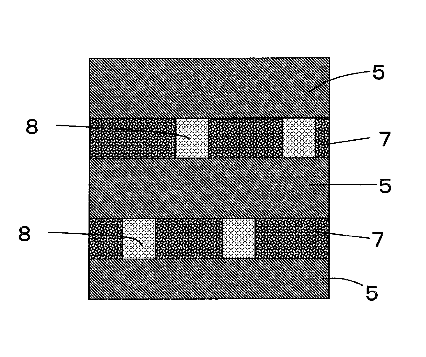
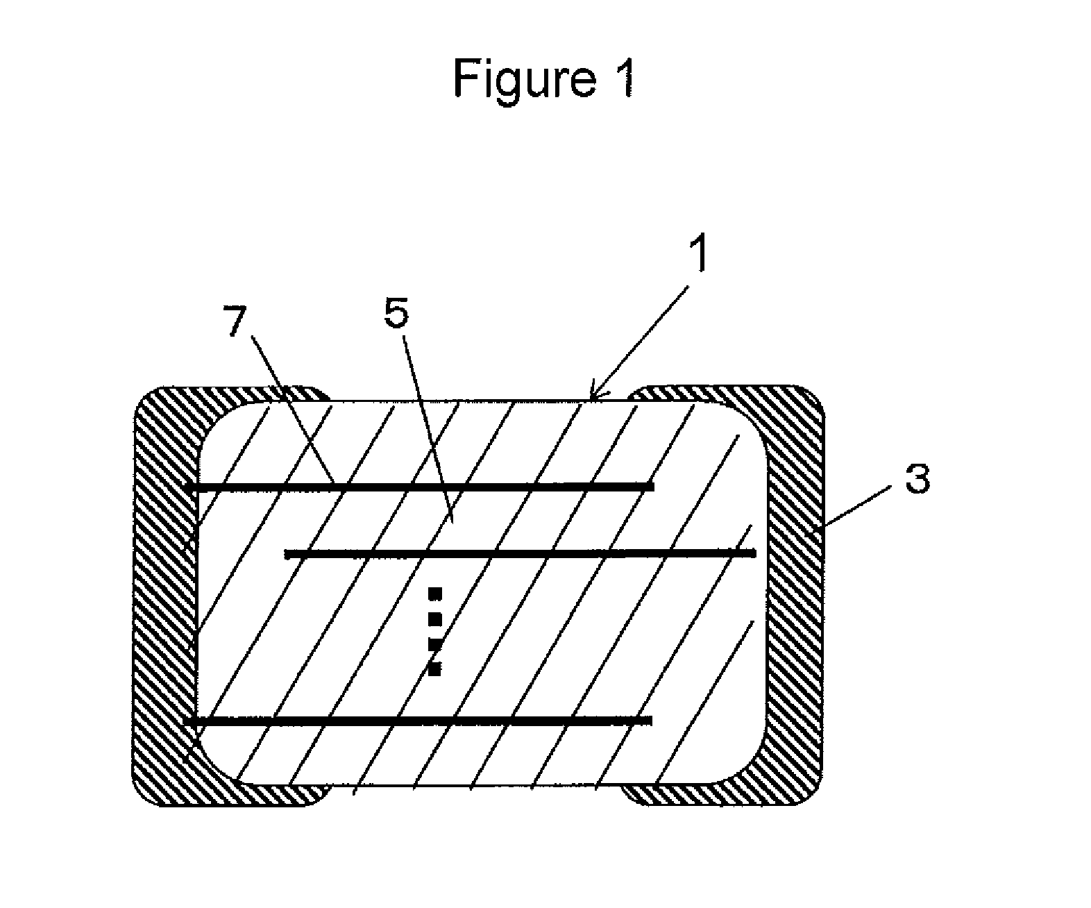
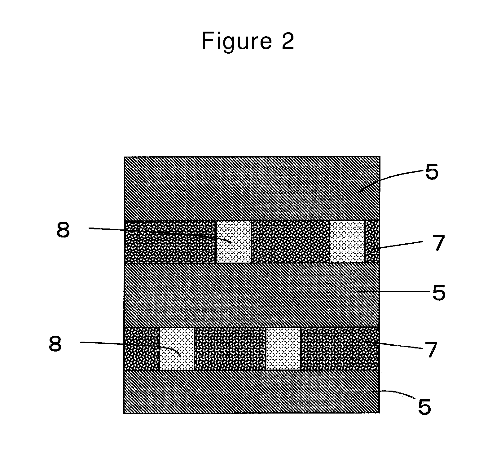
A laminated ceramic capacitor includes a capacitor body of alternately stacked dielectric layers and internal electrode layers, and an external electrode provided on the end face of the capacitor body on which the internal electrode layer is exposed. The dielectric layer has a crystal phase composed mainly of barium titanate and having a cubic system crystal structure. The grain diameter of crystal grains constituting the crystal phase is 0.05 to 0.2 pm. The dielectric layer is formed of a ceramic containing, per mole of barium, 0.0014 to 0.03 moles yttrium, 0.0002 to 0.045 moles manganese, 0.0075 to 0.04 moles magnesium and 0.025 to 0.18 moles ytterbium. The dielectric bonding material is formed of a ceramic containing the same components as those of the main crystal phase of the dielectric ceramic constituting the dielectric layer.

Description

[0001]This application is the National Stage filing of International application No. PCT / JP2009 / 058194 filed on Apr. 24, 2009, which claims priority under 35 U.S.C. §119 to Japanese application No. 2008-113493 filed on Apr. 24, 2008 and Japanese application No. 2008-148512 filed on Jun. 5, 2008.TECHNICAL FIELD[0002]This present invention relates to dielectric ceramic capacitors constituted by crystal grains containing barium titanate as a main component and having a low electrostrictive strain.BACKGROUND ART[0003]Recently, digital electronic devices such as mobile computers and cellular phones are now widely used. Nationwide digital terrestrial broadcasting will start in near future. Receivers for digital terrestrial broadcasting are digital electronic devices such as a liquid crystal display (LCD) and a plasma display. Such digital electronic devices include many large scale integrated circuits (LSI's).[0004]Power circuits constituting digital electronic devices such as a liquid cr...

Claims


Application Information

Patent Timeline
Patent Type & Authority Patents(United States)
IPC IPC(8): H01G4/018C04B35/468
CPCC04B35/46H01G4/1227H01G4/30
Inventor YAMAGUCHI, KATSUYOSHI
Owner KYOCERA CORP
Learn More