
Device and method for detecting degradation of fuel for internal combustion engine

a technology of degradation and internal combustion engine, which is applied in the direction of machines/engines, investigating moving fluids/granular solids, process and machine control, etc., can solve the problems of easy oxidation as compared to conventional fuel, acidity produced by oxidative degradation of biofuels, and adversely affecting the proper execution of fuel injection control, etc., to achieve the effect of higher accuracy and accurate calculation

Inactive Publication Date: 2013-01-08
TOYOTA JIDOSHA KK
View PDF42 Cites 6 Cited by
  • Summary
  • Abstract
  • Description
  • Claims
  • Application Information

AI Technical Summary

Benefits of technology

Enables high-accuracy detection of biofuel degradation, preventing adverse effects on engine components and ensuring reliable fuel injection by providing timely warnings and adjusting fuel injection parameters based on the degradation index.

Problems solved by technology

Since biofuels contain components having an unsaturated bond, they are easily oxidized as compared to conventional fuels.
Oxidative degradation of biofuels produces acids which can corrode metal parts of the fuel system and so on.
When polymerization occurs, the viscosity of fuel increases, which may adversely affect the proper execution of fuel injection control.
When a vehicle has not been driven for along period of time or when the daily travel distance is so short that refueling is not done very often, the biofuel is left in the fuel tank for a long period of time.
Then, degradation may proceed and adverse effects as describe above can occur.
However, a technique for detecting degradation of biofuel with high accuracy has not been established yet.

Method used


Image

  • Device and method for detecting degradation of fuel for internal combustion engine
  • Device and method for detecting degradation of fuel for internal combustion engine
  • Device and method for detecting degradation of fuel for internal combustion engine

Examples


first embodiment

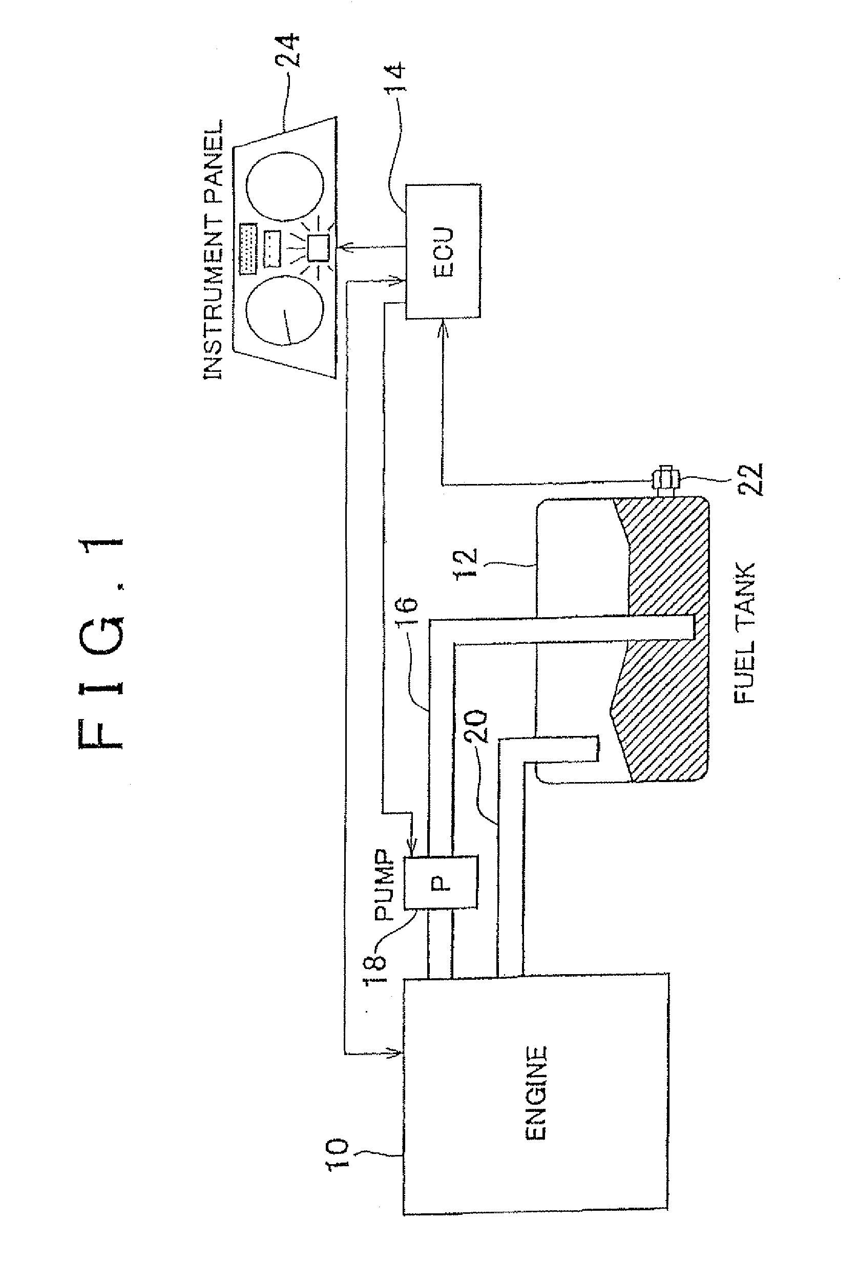
[0034]FIG. 1 is a view illustrating the system configuration of the present invention. As shown in FIG. 1, the system of this embodiment has an internal combustion engine 10 mounted in a vehicle; a fuel tank 12; and an ECU (Electronic Control Unit) 14 that controls the internal combustion engine 10. In this embodiment, the internal combustion engine 10 is a diesel engine.

[0035]The internal combustion engine 10 can be operated by using biofuel. The biofuel may be either 100% biomass-derived fuel produced from biomass or mixed fuel of biomass-derived fuel and other fuel.

[0036]The biofuel in the fuel tank 12 is fed through a fuel pipe 16 to a fuel pump 18 and pressurized therein, and is supplied to the internal combustion engine 10. The biofuel supplied to the internal combustion engine 10 is injected into cylinders from fuel injectors (not shown) provided for each of the cylinders. A portion of the biofuel supplied to the internal combustion engine 10 is returned to the fuel tank 12 t...

second embodiment

[0073]In the second embodiment described above, for the ECU 14 to perform the operation of the routine shown in FIG. 9 can be regarded as the operation of the “degradation index value calculation means” in the present invention, to perform steps 110 and 112 as the operation of the “determination means” in the present invention, and to perform steps 114 and 116 as the operation of the “addition selection means” of the present invention.


PUM

PropertyMeasurementUnit
optical transmittanceaaaaaaaaaa
pressureaaaaaaaaaa
pressureaaaaaaaaaa

Abstract

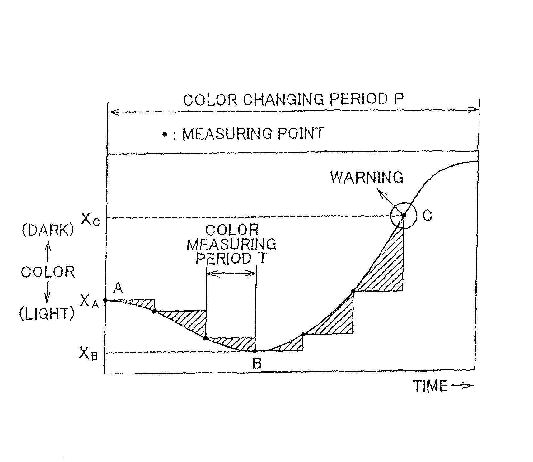
A transmittance sensor that detects the optical transmittance of biofuel is provided on a fuel tank that stores biofuel to be supplied to an internal combustion engine. An ECU periodically acquires the optical transmittance detected by the transmittance sensor, and calculates the amount of change from the previous value. In addition, the ECU calculates a degradation index value indicating the degree of degradation of the biofuel by accumulating the amount of change.

Description

FIELD OF THE INVENTION[0001]The present invention relates to device and method for detecting degradation of fuel for an internal combustion engine.BACKGROUND OF THE INVENTION[0002]Japanese Patent Application Publication No. 2000-130240 (JP-A-2000-130240) discloses a technique for diagnosing the degree of degradation of engine lubricating oil based on the difference in the light absorption loss at each of at least two monochromatic light sources with different wavelengths.[0003]In recent years, there is growing tendency to use biofuels containing fuel produced from biomass as alternative fuels for vehicle engines. Since biofuels contain components having an unsaturated bond, they are easily oxidized as compared to conventional fuels. Oxidative degradation of biofuels produces acids which can corrode metal parts of the fuel system and so on. Also, biofuels can polymerize through reaction with oxygen and so on. When polymerization occurs, the viscosity of fuel increases, which may adve...

Claims


Application Information

Patent Timeline
Patent Type & Authority Patents(United States)
IPC IPC(8): G01N21/00
CPCG01N33/2829
Inventor YOSHIDA, KAORITANIGUCHI, SATOSHI
Owner TOYOTA JIDOSHA KK
Learn More