
Thermal transfer sheet

a technology of thermal transfer sheet and thermal transfer image, which is applied in the field of thermal transfer sheet, can solve the problems of increasing printing speed, increasing the number of thermal transfer sheets, etc., and achieves high transfer sensitivity in thermal transfer printing, high sharpness of thermal transfer images, and high density print

Active Publication Date: 2013-01-01
DAI NIPPON PRINTING CO LTD
View PDF11 Cites 2 Cited by
  • Summary
  • Abstract
  • Description
  • Claims
  • Application Information

AI Technical Summary

Benefits of technology

The present invention provides a thermal transfer sheet which has a high transfer sensitivity in thermal transfer printing to obtain a high density print, has a high sharpness of thermal transfer images, and can prevent abnormal transfer in printing even after being stored at high temperature and high humidity. This is achieved by using an undercoat layer which is made from a liquid containing a water soluble self cross-linking resin, colloidal inorganic pigment ultrafine particles, and aqueous solvent. The water soluble self cross-linking resin cross-links to form a water insoluble network structure, improving the cohesion of the undercoat layer and preventing abnormal transfer of the dye layer. The undercoat layer is made from a liquid containing colloidal inorganic pigment ultrafine particles and a copolymer resin of vinyl pyrrolidone and vinyl acetate, which compensates for the low humidity resistance of polyvinyl pyrrolidone resin. The coating amount of the undercoat layer and the weight ratio of colloidal inorganic pigment ultrafine particles to the copolymer resin are optimized to obtain the printed matter with least “burnt deposit” and prevent the abnormal transfer.

Problems solved by technology

In the thermal transfer recording method utilizing the sublimation transfer, an increase in printing speed of thermal transfer printers has posed a problem that conventional thermal transfer sheets cannot provide satisfactory print density.
Further, high density and high sharpness have become required of prints of images formed by thermal transfer.
However, this method has a problem that wrinkles are caused or even breakage is occurred, due to heat, pressure or the like, during production of the thermal transfer sheet or during thermal transfer recording.
In this method, however, a dye layer is likely to fuse to the image-receiving layer, resulting in an abnormal transfer.
As a result, a high density print cannot be obtained.
Furthermore, since the cohesion of the adhesive layer (undercoat layer) is insufficient, an abnormal transfer occurs in the print after being stored at high temperature and high humidity.
On the other hand, in thermal transfer sheets of Patent Documents 2 and 3, the printed matter obtained by using these transfer sheets does not achieve the sufficient level of the maximum density.
However, thus obtained thermal transfer sheet cannot provide the sufficient sharpness and the sufficiently high density of the thermal transfer image.
Furthermore, the production cost is high, since a special apparatus is required for depositing.
However, the easily adhesive layer shows low transfer sensitivity and cannot provide the high density print, although the adhesiveness with the substrate of the dye layer can be improved.
However, this thermal transfer sheet cannot provide a sufficient level of the print density, although the abnormal transfer can be prevented.
However, this thermal transfer sheet may cause the abnormal transfer, in printing after being stored at high temperature and high humidity.

Method used


Image

  • Thermal transfer sheet
  • Thermal transfer sheet
  • Thermal transfer sheet

Examples


examples

[0080]The present invention will now be explained more in detail, with reference to Examples and Comparative Examples. However, the present invention is not limited to the following Examples. Hereinafter, “parts” or “%” is by weight unless otherwise specified.

example a series

First Embodiment

example a1

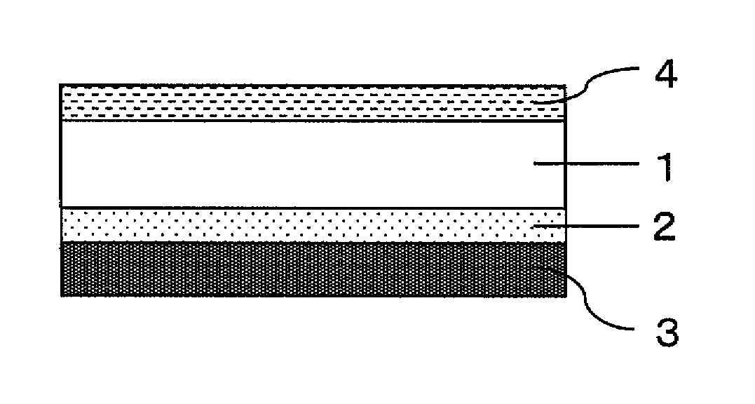
[0081]Onto a substrate, which was polyethylene terephthalate (PET) film having a thickness of 4.5 μm, a coating liquid for an undercoat layer having the following composition was coated by gravure coating with the coating amount of 0.15 g / m2 on a dry basis and dried at 110° C. for 1 minute, so that the undercoat layer was obtained. Onto the undercoat layer, a coating liquid for a dye layer having the following composition was coated by gravure coating with a coating amount of 0.7 g / m2 on a dry basis and dried, so that the dye layer is obtained. Thus, a thermal transfer sheet of Example A1 was obtained. Onto the opposite surface of the substrate, a coating liquid for a heat resistant slip layer having the following composition was coated and dried with a coating amount of 1.0 g / m2 on a dry basis, so that the heat resistant slip layer was obtained.

[0082]

[0083]Alumina sol (Alumina sol 200, feather-like form, NISSAN CHEMICAL INDUSTRIES, LTD., solid content 10%) 10 parts.

[0084]Polyamidep...


PUM

PropertyMeasurementUnit
thicknessaaaaaaaaaa
thicknessaaaaaaaaaa
particle sizeaaaaaaaaaa

Abstract

It is an object of the present invention to provide a thermal transfer sheet which has a high transfer sensitivity in thermal transfer printing to obtain a high density print, has a high sharpness of thermal transfer images, can prevent an abnormal transfer in printing even after being stored at high temperature and high humidity, and can provide a sufficiently satisfactory printed matter.The above object is achieved by a thermal transfer sheet comprising: a substrate; a heat resistant slip layer provided on one side of the substrate; an undercoat layer and a dye layer provided in that order on the other side of the substrate, wherein the undercoat layer is formed by applying and drying a coating liquid which contains, as main components, a water soluble self cross-linking resin and colloidal inorganic pigment ultrafine particles, and cross-linking polymerizing the water soluble self cross-linking resin, or wherein the undercoat layer is formed by using colloidal inorganic pigment ultrafine particles and a copolymer resin of vinyl pyrrolidone and vinyl acetate as main components.

Description

TECHNICAL FIELD[0001]The present invention relates to a thermal transfer sheet provided with: a substrate, on one surface of which a heat resistant slip layer provided on, and on the other surface of which an undercoat layer and a dye layer are provided in that order, in which the undercoat layer contains inorganic oxide and organic resin. More specifically, the present invention relates to a thermal transfer sheet having a high transfer sensitivity during a high speed printing, and allowing a high density print, and preventing abnormal transfer in printing even after being stored at high temperature and high humidity, so that more than satisfactory printed matter is obtained.BACKGROUND ART[0002]Various thermal transfer recording methods have hitherto been known in the art. Among others, a method is proposed to form various full color images by utilizing sublimation dye as a recording material, and thermally transferring the sublimation dye from a thermal transfer sheet onto a trans...

Claims


Application Information

Patent Timeline
Patent Type & Authority Patents(United States)
IPC IPC(8): B41M5/385
CPCB41M5/42B41M5/426B41M5/44B41M2205/02B41M2205/06B41M2205/28B41M2205/38B41M5/382
Inventor YAMASHITA, HIROYUKIISHIDA, TADAHIROHIROSE, KEIJIWATANABE, HIROTAKAKUWABARA, TOSHIKAZUFUKUI, DAISUKEITO, HIDEO
Owner DAI NIPPON PRINTING CO LTD
Learn More