
Antiglare film, antireflective film, polarizing plate and image display device

a technology of anti-glare film and anti-glitter, which is applied in the direction of optics, instruments, optical elements, etc., can solve the problems of reducing display contrast, deteriorating deep black feel, and worsening of glitter traceable to lens effects produced by layer surface asperities, etc., to achieve excellent anti-glare and anti-glitter capabilities, and high density of black

Active Publication Date: 2012-09-04
FUJIFILM CORP
View PDF34 Cites 12 Cited by
  • Summary
  • Abstract
  • Description
  • Claims
  • Application Information

AI Technical Summary

Benefits of technology

[0015]An object of the invention is to provide an antiglare film having excellent anti-glare and anti-glitter capabilities and ensuring high denseness of black. Another object of the invention is to provide an antireflective film not only ensuring excellent anti-glare and anti-glitter capabilities and high denseness of black, but also having a low reflectance. A further object of the invention is to provide a polarizing plate and an image display device each incorporating such an antiglare film or antireflective film.
[0016]As a result of our intensive studies, it has been found that the problems can be solved by acquiring the following aspects, and thereby the objects of the invention can be achieved.

Problems solved by technology

In the case of imparting the antiglare function arising from the surface scatter capability, there however occur problems that an image display screen looks whitish because of its surface scatter capability, resulting in deterioration of a deep-black feel, and glitter traceable to lens effects produced by asperities on the layer surface becomes worse.
The internal scatter capability is utilized for the purpose of improving glitter and viewing angle characteristics of contrast, but when the scattering of light is excessive, there occurs a drawback of lowering display contrast.
On the other hand, when the scattering of light is too little, there occurs a problem that glitter becomes worse.
However, the use of different resin constituents causes a problem that aggregation of light-transmitting particles is apt to occur in light-transmitting resin because of weak affinity between the light-transmitting particles and the light-transmitting resin; as a consequence, surface unevenness become too great, and thereby deterioration of denseness of black is caused.
However, formation of transparent thin films of metal oxides by use of a vapor deposition or sputtering method is low in productivity and not suitable for mass production.
However, when it is tried to coat an uneven surface of an antiglare layer with thin films on a nanometer scale, there may be cases where, since the uneven surface of the antiglare layer gives rise to uneven coating and repelling, the films formed cannot have uniform thickness and optimum optical interference does not occur as it is designed; as a consequence, reflectance is not lowered.
Accordingly, it is difficult to achieve both low reflection and high antiglare properties at the same time.
In this case, however, since the affinity between the light-transmitting particles and the light-transmitting resin is weak, the light-transmitting particles cause aggregation in the light-transmitting resin and form uneven spots on the layer surface.
As a result, there occur problems that the antiglare layer suffers deterioration in a feel of denseness of black and the antireflective film formed thereon cannot have uniform thickness because of uneven coating and repelling of each thin-film layer, and cannot achieve a reflectance drop.

Method used


Image

  • Antiglare film, antireflective film, polarizing plate and image display device
  • Antiglare film, antireflective film, polarizing plate and image display device
  • Antiglare film, antireflective film, polarizing plate and image display device

Examples


example 1

(1) Coating of Antiglare Layer:

[0256]While a roll of 80 μm-thick triacetyl cellulose film (TAC-TD80U, a product of FUJIFILM Corporation) was being wound off, each of the antiglare layer coating solutions shown in Table 2 was coated on the film in accordance with the die coating method using the slot die disclosed in Example 1 of JP-A-2006-122889. Herein, the coating operation was performed at a transport speed of 30 m / min, and the layer coated was dried at 60° C. for 150 seconds, and further cured by irradiation with ultraviolet light from a 160 W / cm air-cooled metal halide lamp (made by Eyegraphics Co., Ltd.) in an exposure dose of 100 mJ / cm2, at an illumination of 400 mW / cm2 under an atmosphere having an oxygen concentration reduced to about 0.1% by the purge using nitrogen, and then wound into a roll. Herein, the amount of each coating solution applied was adjusted so that the thickness of each antiglare layer formed became the value shown in Table 2. Thus, Samples 101 to 112 as ...

example 2

[0290]When each of the film samples made in Example 1 in accordance with the invention was bonded to the glass plate of an organic EL display surface via an adhesive, the amount of light reflected off the glass plate surface was reduced and the resultant display delivered better viewability.

example 3

[0291]A polarizing plate having on one side the antireflective film formed using each of the film samples made in Example 1 in accordance with the invention was made, and to the other side of the polarizing plate, or the side opposite to the antireflective film side, a λ / 4 plate was bonded. The thus made polarizing plate was bonded to the glass plate of an organic EL display surface so that the antireflective film lay at the topmost surface. As a result, surface reflections and reflections from the inside of the surface glass were cut, and the display extremely high in viewability was obtained.

[0292]According to the invention, an antiglare film having excellent anti-glare and anti-glitter properties and ensuring high denseness of black can be offered. And an antireflective film not only ensuring excellent anti-glare and anti-glitter properties and high denseness of black but also having low reflectance values can also be offered. Moreover, the invention can offer antireflective film...


PUM

PropertyMeasurementUnit
particle sizeaaaaaaaaaa
thicknessaaaaaaaaaa
sizesaaaaaaaaaa

Abstract

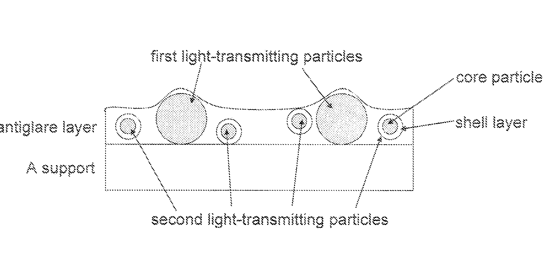
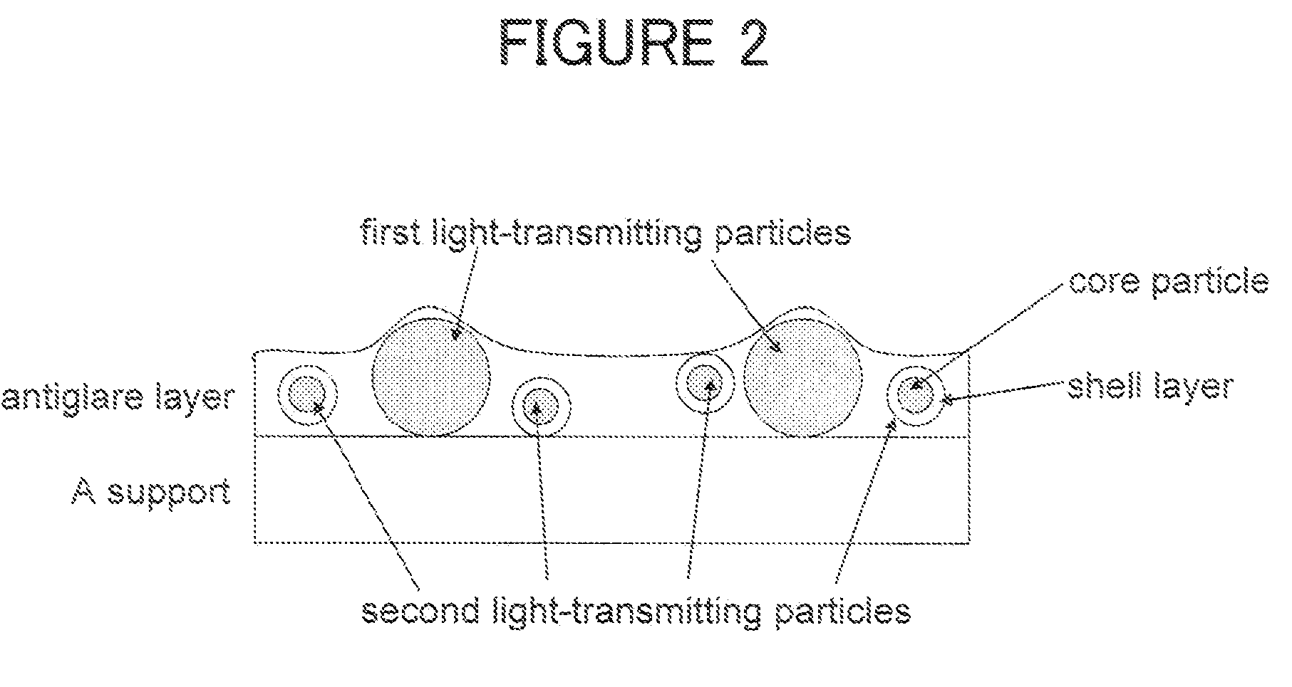
An antiglare film is provided, the antiglare film including: a support; and an antiglare layer including a surface that has asperities, wherein the antiglare layer contains at least first light-transmitting particles and second light-transmitting particles, the first light-transmitting particles have an average particle size that is 0.01 to 2.5 μm greater than an average thickness of the antiglare layer, the second light-transmitting particles have an average particle size that is at least 0.1 μm smaller than the average thickness of the antiglare layer, the first light-transmitting particles are contained in an amount of 0.1 to 2 mass % based on a total solid content in the antiglare layer, the second light-transmitting particles are contained in an amount of 2 to 30 mass % based on the total solid content in the antiglare layer, and the second light-transmitting particles include organic polymer-containing particles each of which has a core particle / shell layer structure.

Description

BACKGROUND OF THE INVENTION[0001]1. Field of the Invention[0002]The present invention relates to an antiglare film, an antireflective film, a polarizing plate and an image display device.[0003]2. Description of the Related Art[0004]In a variety of image display devices, such as a liquid crystal display (LCD), a plasma display panel (PDP), an electroluminescent display (ELD) or a cathode ray tube display (CRT), antiglare film or antiglare antireflective film is used at each individual display surface for the purpose of preventing a contrast drop caused by reflections of extraneous light from the display surface and surroundings' reflection in the display screen. These image display devices are widely used in office and home environments, and an improvement in antiglare capability, or the capability of preventing indoor fluorescent lamps and viewers from being reflected in the display screen, and a further improvement in display contrast in well-lit rooms are required of them (see JP-...

Claims


Application Information

Patent Timeline
Patent Type & Authority Patents(United States)
IPC IPC(8): G02B27/00
CPCG02B5/0221G02B5/0278G02B5/0294
Inventor INOUE, KATSUMISUZUKI, TAKATOWAKIZAKA, DAIKIASAKURA, TETSUYA
Owner FUJIFILM CORP
Learn More