
Methods and systems for chip breaking in turning applications using CNC toolpaths

a technology of cnc toolpaths and cutting tools, applied in process control, process and machine control, instruments, etc., can solve the problems of unbroken chips, largely unattended machining operations, and strong limitations in efficiencies, so as to improve the surface finish, reduce the temperature of the cutting tool, and enhance the ability to implement automated manufacturing cells.

Active Publication Date: 2012-08-14
JUNIVERSITI OF NORT KAROLINA EHT SHARLOTT +1
View PDF8 Cites 10 Cited by
  • Summary
  • Abstract
  • Description
  • Claims
  • Application Information

AI Technical Summary

Benefits of technology

[0007]In various exemplary embodiments, the present invention utilizes dynamically or non-dynamically programmable toolpaths to create short chips, regardless of the cutting conditions present. Machine tool axes capabilities are utilized, not only to position the cutting tool in relation to the workpiece, but also to generate motion that results in short chips. This eliminates the problem of operator exposure to dangerous, and potentially hazardous, materials during the manual chip removal process, reduces the temperature of the cutting tool, and enhances the ability to implement automated manufacturing cells.
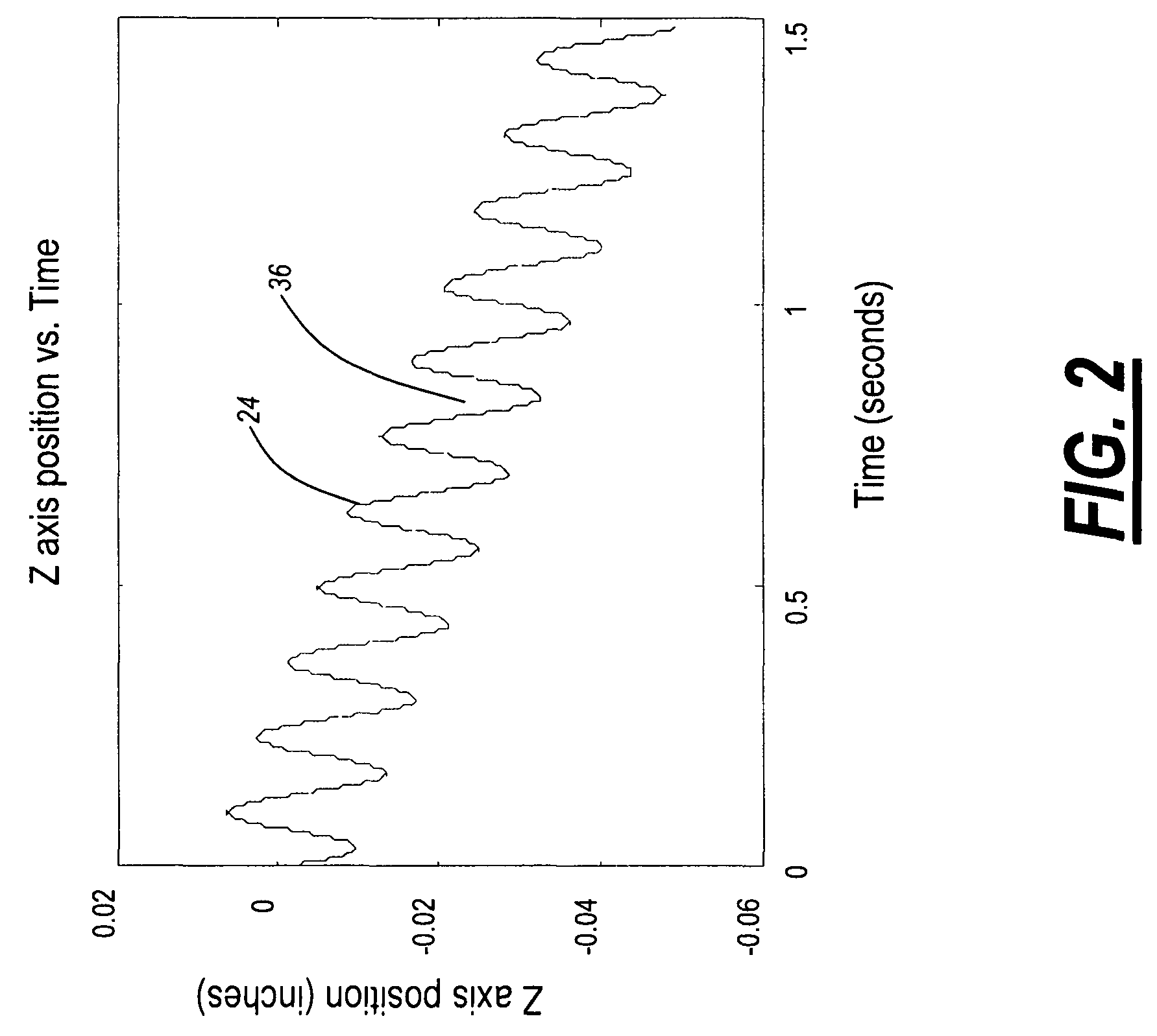
[0008]In one exemplary embodiment, the present invention provides a computer numerical control (CNC)-based method for chip breaking and the like in turning, boring, and other applications, including: engaging a workpiece with a cutting tool in a feed direction along a toolpath; and superimposing an oscillation in the feed direction on the toolpath such that one or more interrupted cuts and one or more chips are produced. The workpiece comprises an axis. The feed direction is one or more of parallel to, perpendicular to, and disposed at an angle to the axis of the workpiece. The oscillation superimposed in the feed direction on the toolpath includes a waveform selected from the group consisting of a sinusoidal waveform, a regular waveform, an irregular waveform, and a random waveform. The method also includes varying a phase of the waveform with one or more of time and workpiece position. The method further includes dynamically or non-dynamically varying the oscillation superimposed in the feed direction on the toolpath. Dynamically or non-dynamically varying the oscillation superimposed in the feed direction on the toolpath includes dynamically or non-dynamically varying one or more of an amplitude, a frequency, and a phase of the oscillation superimposed in the feed direction on the toolpath. Dynamically or non-dynamically varying the oscillation superimposed in the feed direction on the toolpath also includes dynamically or non-dynamically varying the oscillation superimposed in the feed direction on the toolpath based on one or more of an inputted spindle speed, oscillation frequency, oscillation amplitude, cutting tool feed rate, workpiece geometry, part geometry, chip length, probability of producing a predetermined chip length, controller characteristic, machine characteristic, thermal consideration, cutting tool characteristic, part surface texture, residual stress factor, and fatigue life factor. The toolpath is selected responsive to a part surface resulting from a previous toolpath. Optionally, the method is utilized to one or more of control cutting tool wear, manage cutting temperature, create a structured surface, and improve a surface finish.
[0009]In another exemplary embodiment, the present invention provides a computer numerical control (CNC)-based system for chip breaking and the like in turning, boring, and other applications, including: a cutting tool for engaging a workpiece in a feed direction along a toolpath; and a controller for superimposing an oscillation in the feed direction on the toolpath such that one or more interrupted cuts and one or more chips are produced. The workpiece comprises an axis. The feed direction is one or more of parallel to, perpendicular to, and disposed at an angle to the axis of the workpiece. The oscillation superimposed in the feed direction on the toolpath includes a waveform selected from the group consisting of a sinusoidal waveform, a regular waveform, an irregular waveform, and a random waveform. The system also includes an algorithm for varying a phase of the waveform with one or more of time and workpiece position. The system further includes an algorithm for dynamically or non-dynamically varying the oscillation superimposed in the feed direction on the toolpath. Dynamically or non-dynamically varying the oscillation superimposed in the feed direction on the toolpath includes dynamically or non-dynamically varying one or more of an amplitude, a frequency, and a phase of the oscillation superimposed in the feed direction on the toolpath. Dynamically or non-dynamically varying the oscillation superimposed in the feed direction on the toolpath also includes dynamically or non-dynamically varying the oscillation superimposed in the feed direction on the toolpath based on one or more of an inputted spindle speed, oscillation frequency, oscillation amplitude, cutting tool feed rate, workpiece geometry, part geometry, chip length, probability of producing a predetermined chip length, controller characteristic, machine characteristic, thermal consideration, cutting tool characteristic, part surface texture, residual stress factor, and fatigue life factor. The toolpath is selected responsive to a part surface resulting from a previous toolpath. Optionally, the system is utilized to one or more of control cutting tool wear, manage cutting temperature, create a structured surface, and improve a surface finish.
[0010]In a further exemplary embodiment, the present invention provides a computer numerical control (CNC)-based method for chip breaking and the like in turning, boring, and other applications, including: engaging a workpiece with a cutting tool in a feed direction along a first toolpath segment; and engaging the workpiece with the cutting tool in the feed direction along a second toolpath segment; wherein an interaction of the first toolpath segment and the second toolpath segment results in one or more interrupted cuts and one or more chips being produced. Optionally, the method is utilized to one or more of control cutting tool wear, manage cutting temperature, create a structured surface, and improve a surface finish.

Problems solved by technology

In some cases, machining operations are largely unattended.
However, such efficiencies are strongly limited by chip control issues, especially in turning and boring applications.
A common problem in the automation of these applications is the production of continuous, unbroken chips.
These long, stringy chips tend to lead to tangles around the tool and workpiece, potentially damaging both the part and machine.
This problem is largely unpredictable, and, currently, operator intervention is required to avoid and / or remove such tangles, potentially endangering the safety of the operator.
This is especially problematic when dealing with difficult to machine and / or dangerous materials, such as pyrophoric and radioactive materials that must be machined under fluids, in gloveboxes, etc.
In addition, large piles of tangled chips pose a disposal problem.
The use of special cutting tool geometries creates stresses in the chips, causing them to break.
However, these solutions are unreliable, especially in finish turning applications, due to the resultant chips' flexibility.
Current analytical and empirical models are predictively insufficient, and the use of special cutting tool geometries is, essentially, trial and error.
It is common that a chip breaker design that is very effective for one turning application is completely ineffective for another, very similar, turning application.
Disadvantageously, the solutions tend to be part geometry and material specific.
The use of external devices retrofitted to the existing cutting tool to mechanically oscillate the cutting tool tip in and out of the cut in the feed direction is feasible, but problematic.
This solution only works when machining an external part geometry that is aligned with the axes of the machine (e.g., an outer diameter or a face) and does not permit the fabrication of either outer or inner contour surfaces.
It also fails to synchronize the oscillation of the cutting tool tip with the spindle speed (sometimes resulting in a continuous chip), it consumes workspace, and it reduces the stiffness of the cutting process, resulting in a poor quality surface finish.
The use of a high pressure coolant stream directed at the tool-chip interface is only viable for processes with stable chip formation, and has limited effectiveness in contour turning applications with a complex moving tool-chip interface.

Method used


Image

  • Methods and systems for chip breaking in turning applications using CNC toolpaths
  • Methods and systems for chip breaking in turning applications using CNC toolpaths
  • Methods and systems for chip breaking in turning applications using CNC toolpaths

Examples


Embodiment Construction

[0027]The detailed description below summarizes the systems and methods of the present invention in an evolving manner. Initially, simplified cases and solutions are provided to illustrate the basic concepts involved, and more rudimentary techniques. Subsequently, more complicated cases and solutions are provided to illustrate the more advanced concepts involved, and more elegant techniques. It will be readily apparent to those of ordinary skill in the art that different solutions may be preferred in different cases, and various solutions may be combined with one another, as appropriate to the situation. All solutions are exemplary in nature, and should not be construed as limiting in any way.

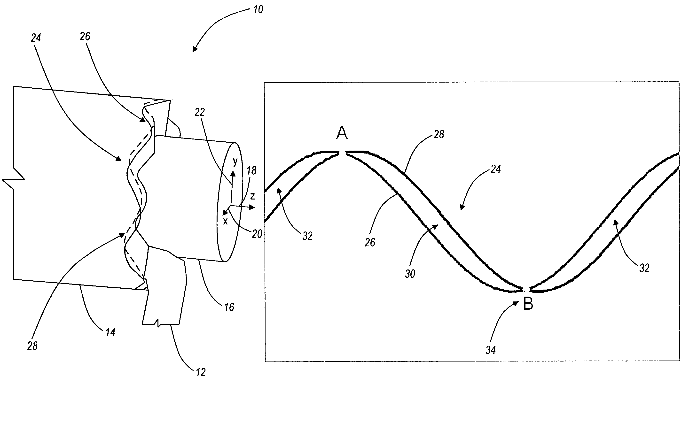
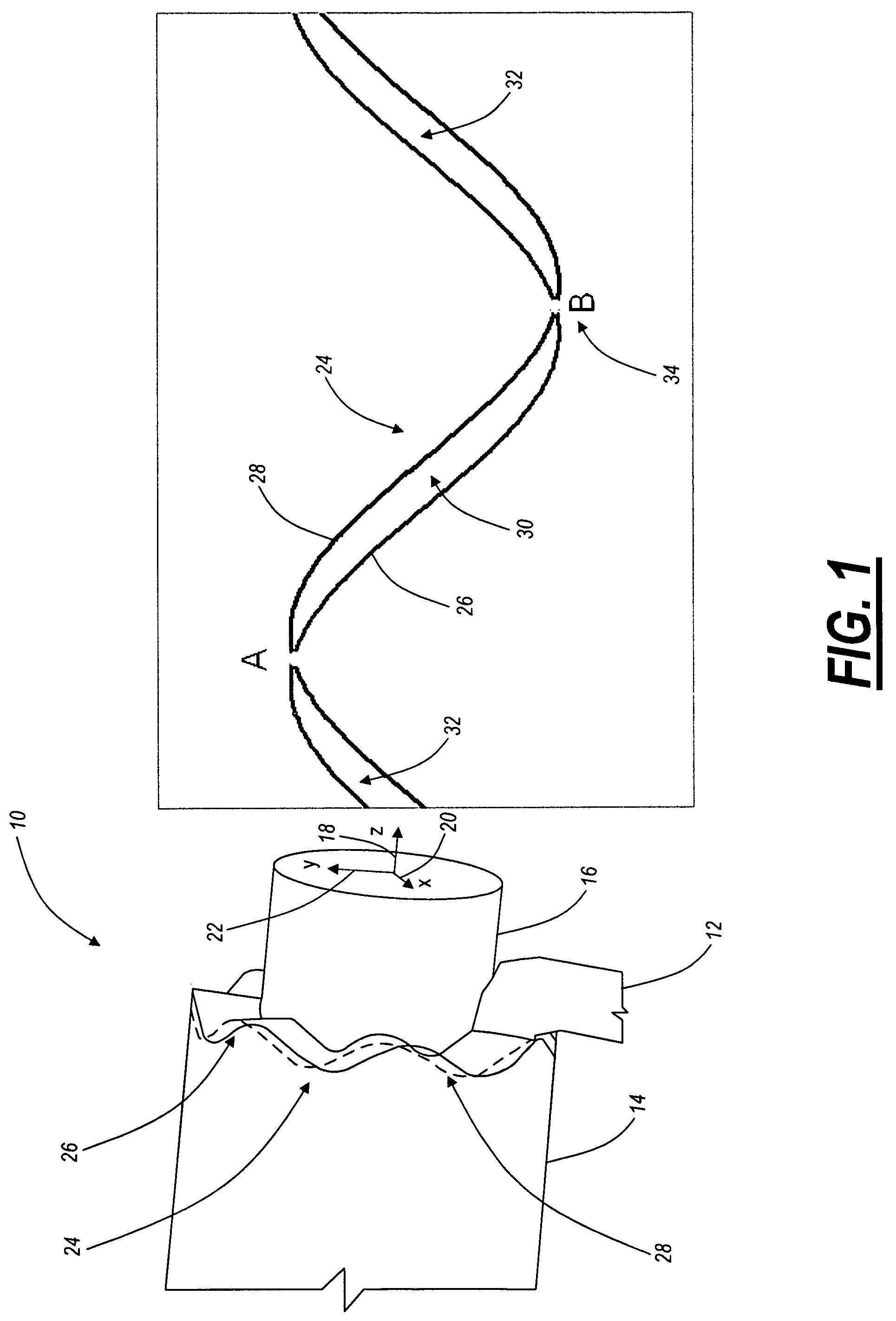
[0028]Referring to FIG. 1, in one exemplary embodiment, the chip breaking system 10 of the present invention includes a cutting tool 12 that selectively engages a workpiece 14 in order to remove material, resulting in a finished part 16. The workpiece 14 and finished part 16 rotate around an ax...


PUM

PropertyMeasurementUnit
depth of cutaaaaaaaaaa
diameteraaaaaaaaaa
depth of cutaaaaaaaaaa

Abstract

The present invention provides methods and systems for chip breaking, controlling cutting tool wear, and the like in turning, boring, and other applications, including: engaging a workpiece with a cutting tool in a feed direction along a toolpath, superimposing an oscillation in the feed direction on the toolpath, and dynamically or non-dynamically varying the oscillation superimposed in the feed direction on the toolpath such that interrupted cuts and chips of a predetermined length or less are produced. These systems take full advantage of computer numerical control (CNC) methodologies.

Description

CROSS-REFERENCE TO RELATED APPLICATION(S)[0001]The present non-provisional patent application claims the benefit of priority of U.S. Provisional Patent Application No. 60 / 980,276, filed on Oct. 16, 2007, and entitled “CNC TOOLPATHS FOR CONTROLLING THE CHIP BREAKING PROCESS IN TURNING APPLICATIONS,” the contents of which are incorporated in full by reference herein.STATEMENT REGARDING FEDERALLY SPONSORED RESEARCH OR DEVELOPMENT[0002]The U.S. Government has a paid up license in this invention and the right, in limited circumstances, to require the patent owner to license to others on reasonable terms as provided for by the terms of Contract No. DE-AC05-00OR22800 between the U.S. Department of Energy and Babcock & Wilcox Technical Services Y-12, L.L.C.FIELD OF THE INVENTION[0003]The present invention relates generally to methods and systems for chip breaking, controlling cutting tool wear, and the like in turning, boring, and other applications using computer numerical control (CNC) to...

Claims


Application Information

Patent Timeline
Patent Type & Authority Patents(United States)
IPC IPC(8): B23Q15/14B23Q15/26
CPCB23B1/00B23B35/00Y10T82/10Y10T82/2502G05B2219/37598B23B25/02G05B2219/49055
Inventor WOODY, BETHANY A.SMITH, KEVIN SCOTTADAMS, DAVID J.BARKMAN, WILLIAM E.BABELAY, JR., EDWIN F.
Owner JUNIVERSITI OF NORT KAROLINA EHT SHARLOTT
Learn More