Electromagnetic wave resonator, method of manufacturing the same, and method of resonating electromagnetic wave
a technology of electromagnetic waves and plasmon resonances, applied in waveguide devices, instruments, optical elements, etc., can solve the problems of insufficient reproducibility and reliability, inability to easily use plasmon resonances in nanoparticle systems as resonators, and limited gap sizes, etc., to maximize electromagnetic energy and excellent reproducibility and efficiency.
- Summary
- Abstract
- Description
- Claims
- Application Information
AI Technical Summary
Benefits of technology
Problems solved by technology
Method used
Image
Examples
first example
[0076]First Example illustrates an open resonator, in which gold is employed for a dielectric and surface plasmon is used as a surface wave, for an electromagnetic wave in the regions from visible light to infrared light.
[0077]First, as shown in FIG. 6(a), a first negative dielectric thin film 1, a positive dielectric thin film 3, and a second negative dielectric thin film 2 were formed on a substrate 10 in this order. In this Example, a synthetic quartz substrate was employed for the substrate 10. On this substrate, a gold thin film with a thickness of 150 nm as the first negative dielectric thin film 1, a silica (SiO2) thin film with a thickness D as the positive dielectric thin film 3 and a gold thin film with a thickness of 150 nm as the second negative dielectric thin film 2 were stacked.
[0078]The gold thin films were formed by DC magnetron sputtering and the silica thin film was formed by high frequency magnetron sputtering. A chromium film with a thickness in a range from 5 n...
second example
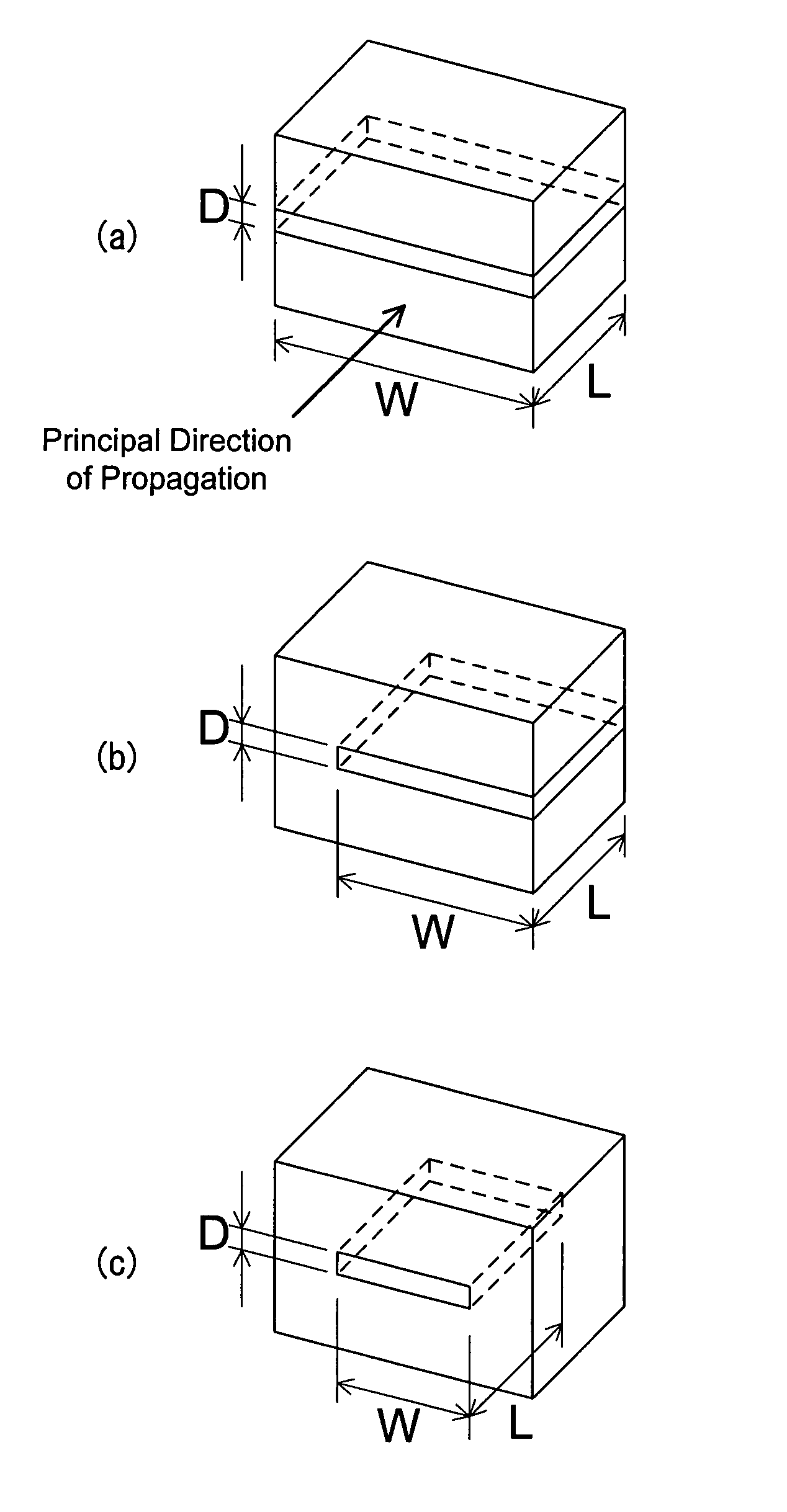
[0098]The second Example was to realize a closed resonator under the conditions almost same as the first Example. The same procedure as the first Example was carried out until forming a stacked film of a first negative dielectric thin film (a gold thin film) 1, a positive dielectric thin film (a silica thin film) 3 and a second negative dielectric thin film (gold) 2 on a substrate (a synthetic quartz substrate) 10 and removing the outside by focused ion beam so as to leave the rectangular resonator with a length L′ and a width W′ (FIG. 9(a)). The length L′ and the width W′ should be defined rather large in size, such as 500 nm. The depth for removal should be at least so deep as to pass through the second negative dielectric thin film 2.
[0099]The substrate was moved into a resistive heating vacuum evaporator to deposit a gold thin film with a thickness of 150 nm as a third negative dielectric thin film 4 (FIG. 9(b)). In this process, the substrate was positioned to be 45 degrees obl...
third example
[0103]In the third Example, a resonator is described that has a plurality of the resonance structures as described in the first and the second Examples aligned therein. It is important for practical use to realize a resonator aligned to interact with electromagnetic waves emitted to a wide region.
[0104]A method of manufacturing a resonator having a plurality of open resonator structures aligned therein is illustrated here. First, a multilayer (a multilayer structure) 11 is formed in which a gold thin film with a thickness of 150 nm as a negative dielectric thin film 7 and a silica thin film with a thickness D as a positive dielectric thin film 3 were stack with each other a plurality of times on a synthetic quartz substrate as a substrate 10 (FIG. 10(a)).
[0105]Subsequently, the substrate 10 was cut into strips each with a width of, for example, 2 mm. One of the strips was paired with another and the multilayer structure parts were bonded with a hard epoxy resin to be a junction laye...
PUM
| Property | Measurement | Unit |
|---|---|---|
| thickness | aaaaa | aaaaa |
| thickness | aaaaa | aaaaa |
| vacuum wavelength λ0 | aaaaa | aaaaa |
Abstract
Description
Claims
Application Information
 - R&D
- Intellectual Property
- Life Sciences
- Materials
- Tech Scout
- Unparalleled Data Quality
- Higher Quality Content
- 60% Fewer Hallucinations
Browse by: Latest US Patents, China's latest patents, Technical Efficacy Thesaurus, Application Domain, Technology Topic, Popular Technical Reports.
© 2025 PatSnap. All rights reserved.Legal|Privacy policy|Modern Slavery Act Transparency Statement|Sitemap|About US| Contact US: help@patsnap.com


