
Helmet and body armor actuated ventilation and heat pipes

Active Publication Date: 2012-04-17
HOCKADAY ROBERT G
View PDF28 Cites 44 Cited by
  • Summary
  • Abstract
  • Description
  • Claims
  • Application Information

AI Technical Summary

Benefits of technology

[0012]The use of body armor, helmets, fire proof suits, hazardous environment suits, cock pit shells, thick garments, shoes, and gloves on people such as motor cross racing drivers, racing car drivers, soldiers, police, and firefighters can lead to excessive temperatures on the wearers body. The human body reaction to maintain constant temperature is to sweat and cool by evaporation on the skin. Due to the confined conditions and lack of air circulation under the armor the sweating does not result in evaporation and effective cooling of the wearer. Thus sweat builds up under the armor and the wearer becomes uncomfortable, this can result in dehydration, in some situations even possibly lead to hyperthermia or hypothermia. In addition the moist and warm conditions on the skin are ideal growth conditions for bacterial growth and can lead to skin and wound infections of the wearers. Body oils from the wearer can also interfere with efficient wicking of sweat. In cold weather environments excessive cooling through body armor can also lead to an opposite situation of chilling the wearer of the armor.
[0013]The disclosed invention is to provide a means of wicking sweat off the body and skin onto a wicking surface covering the padding or of the of the body armor, and creating air flow passages in the padding of the helmet or body armor to allow for effective cooling by evaporation of the sweat from the wearer. Padding contact and confinement of the body armor interferes with the normal evaporative cooling of sweating and evaporation to air flow. By placing thermally conductive materials, or heat pipes inside the padding to transfer heat on contact with the body and with the evaporating sweat areas onto the wicking surfaces it restores the cooling effect of sweating. To provide optimum heat removal control to maintain desirable temperatures and humidity surrounding the wearer, humidity or temperature bi-material laminate actuating valves open to let air flow when temperatures or humidity are high to maximize air flow and evaporation and close when the temperatures are low or humidity is low to retain heat and maintain a comfortable environment about the wearer. The laminate actuators can be distributed through out the air vent channels under the body armor to achieve local control thereby uniformly maintaining desirable environmental conditions through out the apparel. Laminate actuators in the form of exterior layers or fabric can be used to cover the exterior of the body armor or helmet to act as self adjusting variable thermal insulation and ventilation to the body armor and thermally conductive elements. To insure the cooling effect of flowing air in high humidity environments water absorbent and heat dissipation an air intake filter be used to de-humidify the air flow entering the system. The air intake filter can also be an insect, dust and / or bacterial filter to keep the air flow space inside the armor clean. An air fan can be used to pump air through the system when the system is stationary or high power cooling performance is needed or the air flow resistance into passages will not allow sufficient evaporative cooling to be effective. The padding and wicking surfaces can be treated with antibacterial coating to prevent fungal and bacterial growth. Water can be distributed to the evaporating areas with tubes or membranes onto of the thermal conductors or heat pipes for additional cooling. This patent application incorporates laminated actuators of our filed patent application U.S. Ser. No. 11 / 702,821, filed Feb. 6, 2007, based on U.S. Provisional Application 60 / 765,607, filed Feb. 6, 2006 “Laminate Actuators and Valves” as if fully set forth herein as an air and heat flow control mechanism because of their simplicity, unique low mass and structural formability to be incorporated into apparel.

Problems solved by technology

This patent application does not integrate the heat pipe into apparel or animal contact.
Excessive sweating of wearer can lead to discomfort, skin irritation and dehydration.

Method used


Image

  • Helmet and body armor actuated ventilation and heat pipes
  • Helmet and body armor actuated ventilation and heat pipes
  • Helmet and body armor actuated ventilation and heat pipes

Examples


Embodiment Construction

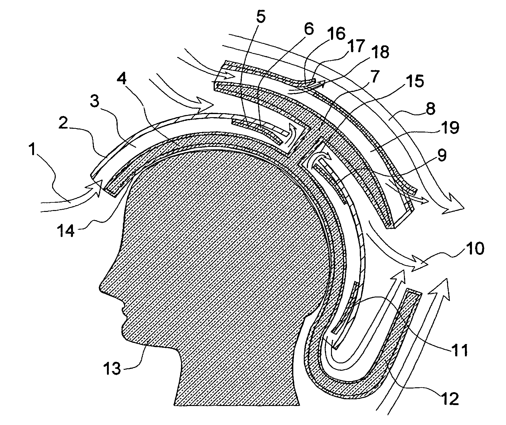
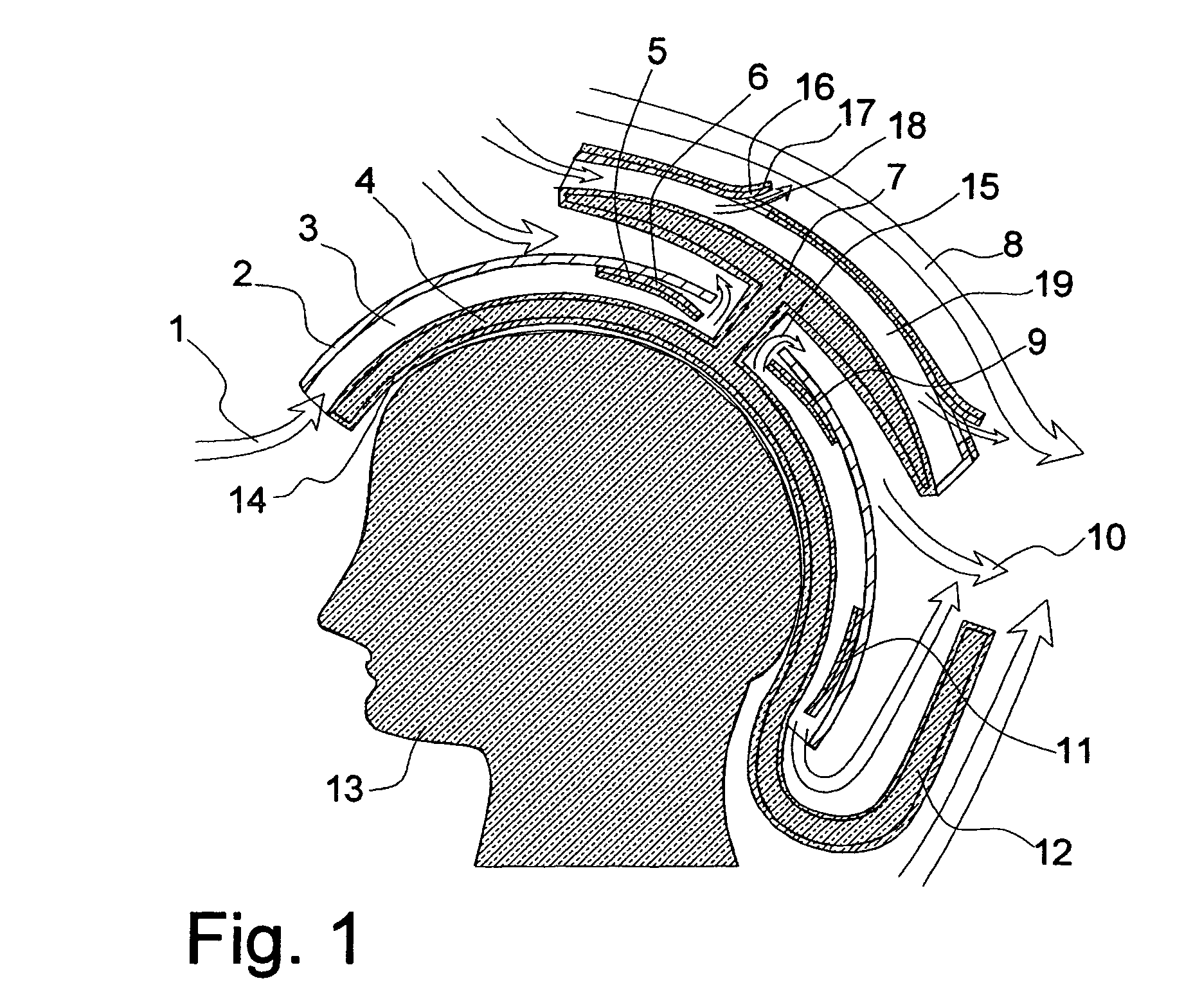
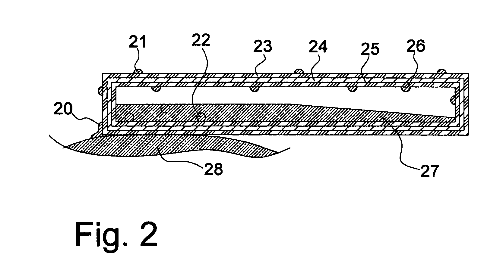
[0138]Several typical embodiments of the invention are illustrated in the following frames. In these drawings several variations in assembly and arrangements will be shown. Please note that the drawings are drawn disproportionately to illustrate the physical features of this invention. In FIG. 1 a cross sectional view of helmet on a human head is shown. In a typical application the protective shell or helmet 2 is made of Kevlar and polyester resin lamination or steel. The padding 4 on the head of the human 13 is open cell urethane or closed cell neopream foam with a silk covering over the urethane foam. Inside the padding are flexible or rigid heat pipes. Rigid heat pipes 4 can be formed out of stainless steel or copper and the working fluid can be water, butane, or fluorocarbons such as perfluorhexane, 2-methyl perfluorpentane 1,1 difluroethane, 1,1,1,2-tetrafluroethane. Flexible heat pipes 4,7,12 can be formed out of aluminum foil sandwiched between polyester and polypropylene lam...


PUM


Abstract

The lack of air flow under body armor, helmets, and thick garments can lead to excessive moisture build up and discomfort on the wearers body due to lack of heat removal and effective evaporation of sweat. By incorporating wick covered heat pipes or thermal conductors with air flow channels in the apparel contact area between the garments, helmets, and body armor the effectiveness air flow cooling and evaporation of sweat can be restored. Humidity or temperature auto-actuated bi-material valves are used to control this air-moisture-heat flow to achieve a controlled comfortable humidity-temperature environment and avoid excessive cooling. Supplementary air pumps, filters, dehydrators, fluid pumps, heating fluids, and cooling fluids may be incorporated to enhance the effectiveness. Biocides and hydrophilic materials are also incorporated on the wick coverings to avoid biological growth and maintain performance to achieve a healthy environment for the wearer.

Description

[0001]This application claims the benefit of U.S. Provisional Application No. 61 / 062,219, filed Jan. 24, 2008, which is hereby incorporated by reference in its entirety.SUMMARY OF THE INVENTION[0002]The invention provides apparatus to control the movement of heat and moisture and control temperature and humidity, by evaporation and air cooling with air flow between an armor shell, apparel, or helmet covering human or animal body using; air flow channels, water wicking material covered heat pipes, or thermal conductors in contact with human or animal body and humidity and / or temperature reactive auto-actuated laminate impedance structures or humidity and / or temperature reactive auto-actuated laminate valves.[0003]The invention provides apparatus to control the movement of heat and chemicals and thereby control temperature and humidity, by evaporation and air cooling with fluid flow between a cover over a living body using fluid flow channels, liquid wicking material covered thermal c...

Claims


Application Information

Patent Timeline
IPC IPC(8): A42B3/28
CPCA41D13/0025A42B3/285Y10T428/24463
Inventor HOCKADAY, ROBERT G.
Owner HOCKADAY ROBERT G
Learn More