
Sulfuric acid electrolytic cell and a sulfuric acid recycle type cleaning system applying the sulfuric acid electrolytic cell

a sulfuric acid electrolytic cell and electrolytic cell technology, applied in the direction of electrical-based machining electrodes, electrode coatings, manufacturing tools, etc., can solve the problems of over-all cracking, and affecting the performance of the electrolytic cell. , to achieve the effect of preventing corrosion, superior mechanical strength and high durability

Active Publication Date: 2012-03-20
DE NORA PERMELEC LTD +2
View PDF13 Cites 8 Cited by
  • Summary
  • Abstract
  • Description
  • Claims
  • Application Information

AI Technical Summary

Benefits of technology

The design provides a mechanically robust and durable sulfuric acid electrolytic cell that withstands severe electrolysis conditions, prevents corrosion, and maintains high efficiency in producing persulfuric acid for semiconductor cleaning, meeting the stringent purity requirements of the semiconductor industry.

Problems solved by technology

Impurities in sulfuric acid available in the market for the semiconductor manufacturing process have been controlled on the ppb level; however persulfate produced on an industrial level contains impurities as much as over 1000 times, cleanliness level of which, therefore, does not meet at all the level for the semiconductor cleaning process.
This pressure is directly applied to the electrode surface, and if deflectable stress is loaded on the electrode, overall cracking may occur.
Silicon is a material which is relatively hard, but brittle, having cleavage and therefore, the silicon substrate tends to be wholly destroyed once break occurs.
In particular, when there is a freely moving end and a supporting point on the silicon substrate, any break or crack occurring from a part of the silicon substrate could develop to a wholly breakage.
Such pressing force on the electrode surface tends to be uneven because of multiple numbers of coil springs, causing breakage of electrodes or leakage of liquid easily, while, on the other hand, local adjustment is available spot-wise on the electrode surface.
If the electrode attached to the conductive supporting disc is considered as an integral unit, an entire breakage of the electrode is hard to occur when the supporting disc is thick enough, but still breakage is easy to occur where pressing force is locally large.
Therefore, the construction of this electrolytic cell has drawback in terms of easy breaking and cracking.
In Patent Document 4, pressing force to the current collector is applied by multiple numbers of springs and conductive metal fiber construction having elasticity, as with the method by Patent Document 2, and therefore, similar problems to Patent Document 2 could occur.
Whereas, the specification explains that in order to obtain uniform pressing force, conductive metal fibers are employed; however, in fact, conductive metal fibers have elasticity, which allows significant change in thickness by pressing force and therefore, it should be difficult to compress the large area to a uniform thickness.
In view of this, the displacement in thickness with the electrolytic cells described in Patent Document 4 will cause deflection, which will lead to generation of cracking.
In addition, compression deformation of conductive metal fibers generates resistance by conductive metal fibers themselves or distribution of contact resistance by conductive metal fibers with diamond electrodes or with the current collector, which leads to uneven distribution of electrolytic current or Joule heat, eventually causing local loading on electrodes or electrolytic cells or variation in performance.

Method used


Image

  • Sulfuric acid electrolytic cell and a sulfuric acid recycle type cleaning system applying the sulfuric acid electrolytic cell
  • Sulfuric acid electrolytic cell and a sulfuric acid recycle type cleaning system applying the sulfuric acid electrolytic cell
  • Sulfuric acid electrolytic cell and a sulfuric acid recycle type cleaning system applying the sulfuric acid electrolytic cell

Examples


example 1

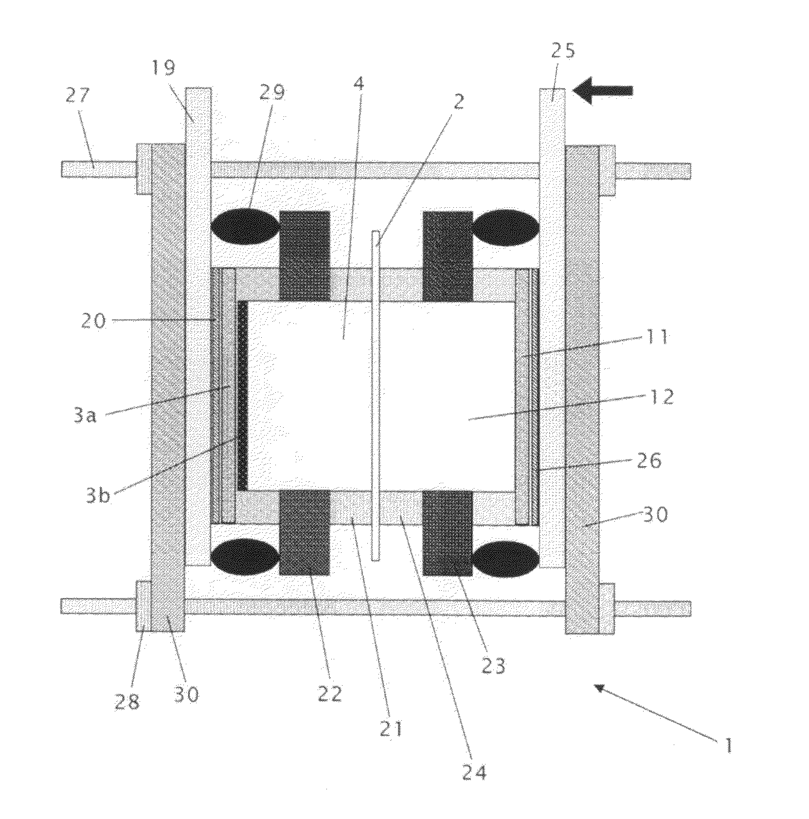
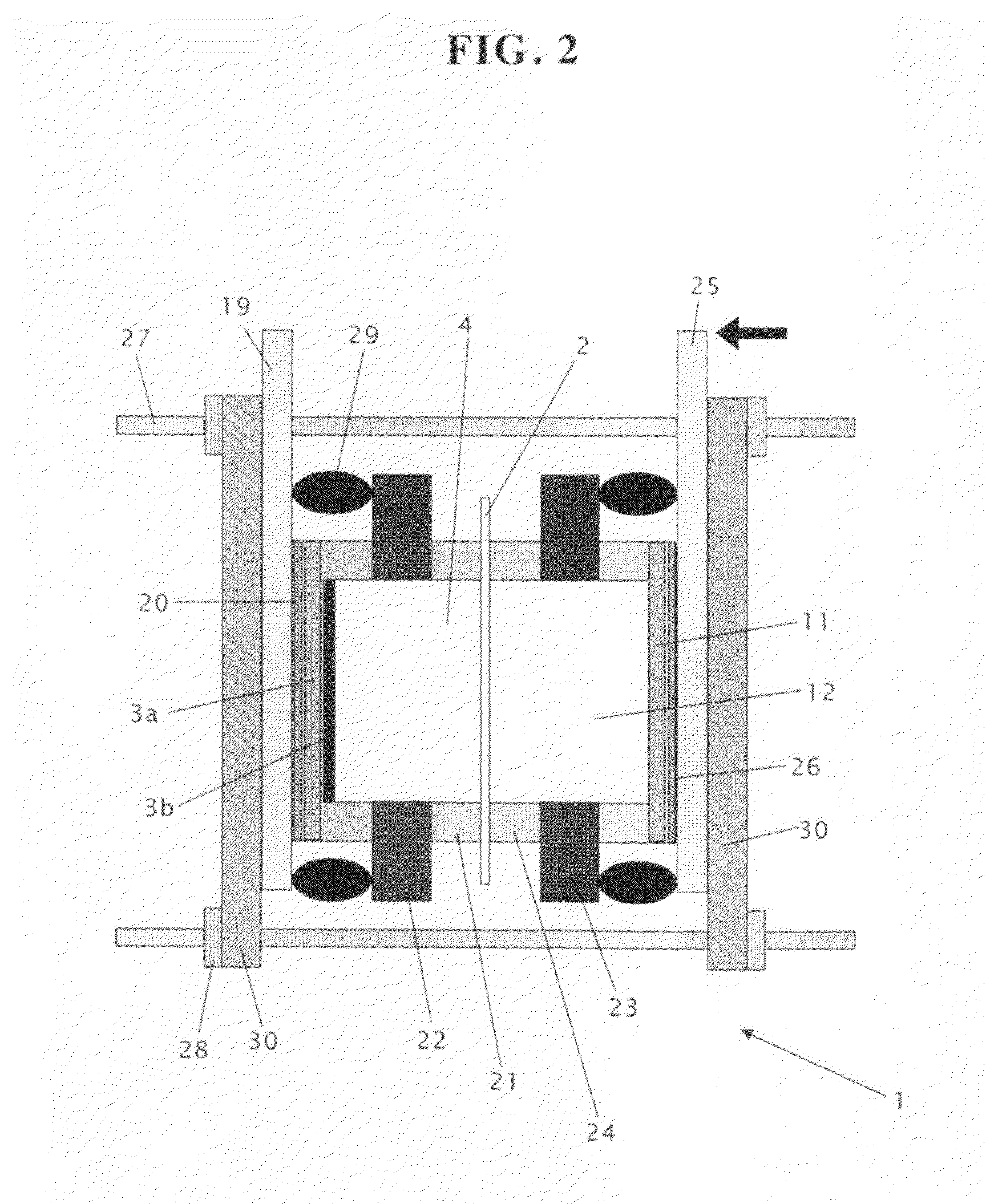
[0070]On a silicon base material (substrate) of 3 mm thick, 6 inch diameter, a diamond layer of 20 μm was formed by the microwave plasma CVD method applying methane and diborane (10000 ppm to methane) as raw material to be used as the conductive diamond anode. A proper amount of conductive paste (Fujikura Kasei D 550) was applied as adhesive agent over the entire area of the rear face of this anode; and this anode was attached to the center part of the copper current collector of 17 cm dia. with a conductive rib and underwent the hardening treatment for 30 minutes at 100 degree Celsius in an oven to obtain an current collector with a conductive diamond anode and an current collector with a conductive diamond cathode.

[0071]Then, an end plate, an current collector with a conductive diamond anode, a porous PTFE gasket, a cell frame, a porous PTFE gasket, a diaphragm, a porous PTFE gasket, a cell frame, a porous PTFE gasket, an current collector with a conductive diamond cathode, and an...

example 2

[0107]On a silicon base material (substrate) of 3 mm thick, 6 inch diameter, a diamond layer of 20 μm was formed by the microwave plasma CVD method applying methane and diborane (10000 ppm to methane) as raw material to be used as the conductive diamond electrode. A proper amount of conductive paste (Fujikura Kasei D 550) was applied as adhesive agent over the entire area of the rear face of this electrode; and this electrode was attached to the center part of the copper current collector of 17 cm dia. with a conductive rib and underwent the hardening treatment for 30 minutes at 100 degree Celsius in an oven to obtain an current collector with a conductive diamond anode and an current collector with a conductive diamond cathode.

[0108]Then, an end plate, an current collector with a conductive diamond electrode, a porous PTFE gasket of 5.6 inch periphery dia. and 1.0 cm periphery width and a Viton o-ring of 6 inch periphery dia. and 2 mmφ cross section dia. (=gasket+o-ring), a PTFE ce...


PUM

PropertyMeasurementUnit
electrolytic current densityaaaaaaaaaa
thickaaaaaaaaaa

Abstract

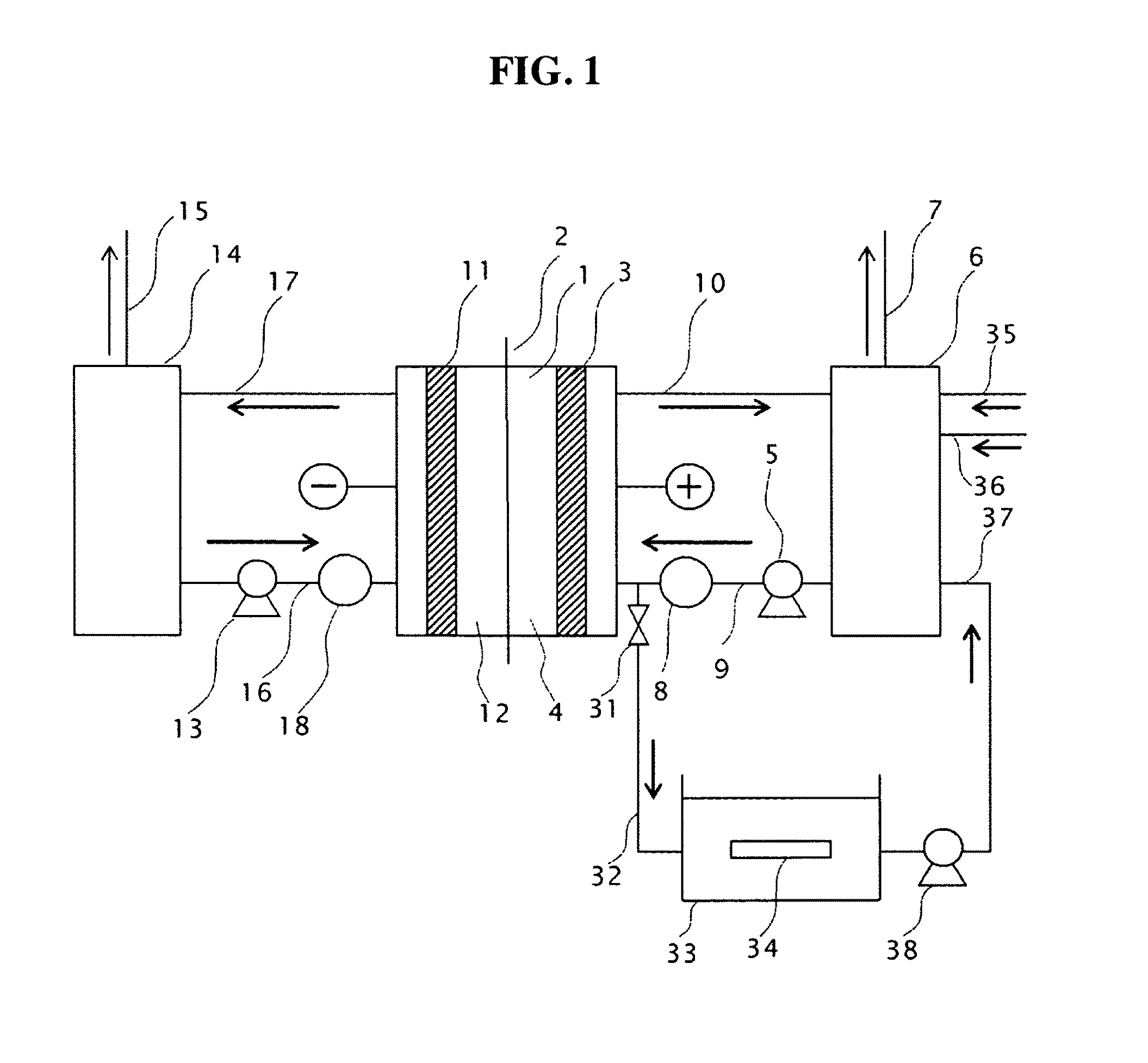
In a sulfuric acid electrolytic cell to electrolyze sulfuric acid supplied to an anode compartment and a cathode compartment comprising a diaphragm, said anode compartment and said cathode compartment separated by said diaphragm, a cathode provided in said cathode compartment and a conductive diamond anode provided in said anode compartment, as said conductive diamond anode, a conductive diamond film is formed on the surface of said conductive substrate, the rear face of said conductive substrate is pasted, with conductive paste, on an current collector comprising a rigid body with size equal to, or larger than, said conductive substrate, an anode compartment frame constituting said anode compartment is contacted via gasket with the periphery on the side of the conductive diamond film of said diamond anode, said diaphragm is contacted with the front face of said anode compartment, further, with the front face of said diaphragm, the cathode compartment frame constituting said cathode compartment, a gasket, and said cathode are contacted in sequence, the rear face of said cathode is pasted with conductive paste to the current collector comprising a rigid body with size equal to, or larger than, said cathode and electric power is supplied from one current collector to the other current collector via said conductive paste.

Description

CROSS-REFERENCE TO RELATED APPLICATIONS[0001]This application is based upon and claims the benefit of priority of Japanese Patent Application 2008-170096, filed on Jun. 30, 2008; the entire contents of which are incorporated herein by reference.BACKGROUND OF THE INVENTION[0002]1. Field of the Invention[0003]The present invention relates to a sulfuric acid electrolytic cell which forms a solution containing chemical species of oxidation nature through electrolysis of sulfuric acid and a sulfuric acid recycle type cleaning system applying the sulfuric acid electrolytic cell.[0004]2. Description of the Related Art[0005]It is reported that electrolyzed water with oxidation nature or reduction nature being formed through water electrolysis can be utilized in various areas including medical and foods industries.[0006]Also, in the cleaning process of electronics components, cleaning with electrolyzed water commands attention for its less danger in storage or transportation available by the...

Claims


Application Information

Patent Timeline
Patent Type & Authority Patents(United States)
IPC IPC(8): C25B9/08C25B1/28C25B11/12C25B9/19
CPCC25B9/00C25B1/285C25B1/29C25B9/23C25B11/046C25B11/083
Inventor KATO, MASAAKISEYA, YOSHIYUKIHAYAMIZU, NAOYATANGE, MAKIKOKUROKAWA, YOSHIAKIKOBAYASHI, NOBUO
Owner DE NORA PERMELEC LTD
Learn More