Biosensor based on polymer cantilevers

a biosensor and polymer technology, applied in the field of polymer cantilevers, can solve the problems of high cost of optical systems, inability to miniaturize systems, and inability to process high density sensor arrays, and achieve the effect of easy and inexpensive processing

Inactive Publication Date: 2012-02-28
WAYNE STATE UNIV
View PDF9 Cites 1 Cited by
  • Summary
  • Abstract
  • Description
  • Claims
  • Application Information

AI Technical Summary

Benefits of technology

[0012]The present invention overcomes the problems encountered in the prior art by providing in one embodiment a cantilever sensor comprising a supporting substrate, a cantilever spring element at least partially disposed over the support substrate, a probe layer disposed over the first side of the cantilever spring element, and a piezoresistive transducer attached to the second side of the cantilever spring element. The cantilever spring element is characterized by having a first side and a second side and comprising a polymer having a Young's modulus less than about 100 Gpa,. Sensing systems that incorporate the cantilever sensor of the invention include a detector in communication with the piezoresistive transducer to provide measurements of surface strain changes in the piezoresistive transducer. The cantilever sensors of the invention advantageously allow for a label-free assay. Moreover, the cantilever sensors of the invention are miniaturizable and portable with the bulky optical components of the prior art systems being eliminated. Reduction in the cantilever dimensions allows for high density sensor arrays to be fabricated. Since the output from the piezoresistive transducer is an electrical signal, these signals are easily and inexpensively processed.

Problems solved by technology

First, the system can not be miniaturized.
Second, the optical system is expensive (a laser source and a photosensor with associated readout circuits can easily exceed $2000).
Third, it is difficult to monitor large 2-D cantilever arrays using optical lever method.

Method used


Image

  • Biosensor based on polymer cantilevers
  • Biosensor based on polymer cantilevers
  • Biosensor based on polymer cantilevers

Examples


Embodiment Construction

)

[0022]Reference will now be made in detail to presently preferred compositions or embodiments and methods of the invention, which constitute the best modes of practicing the invention presently known to the inventors.

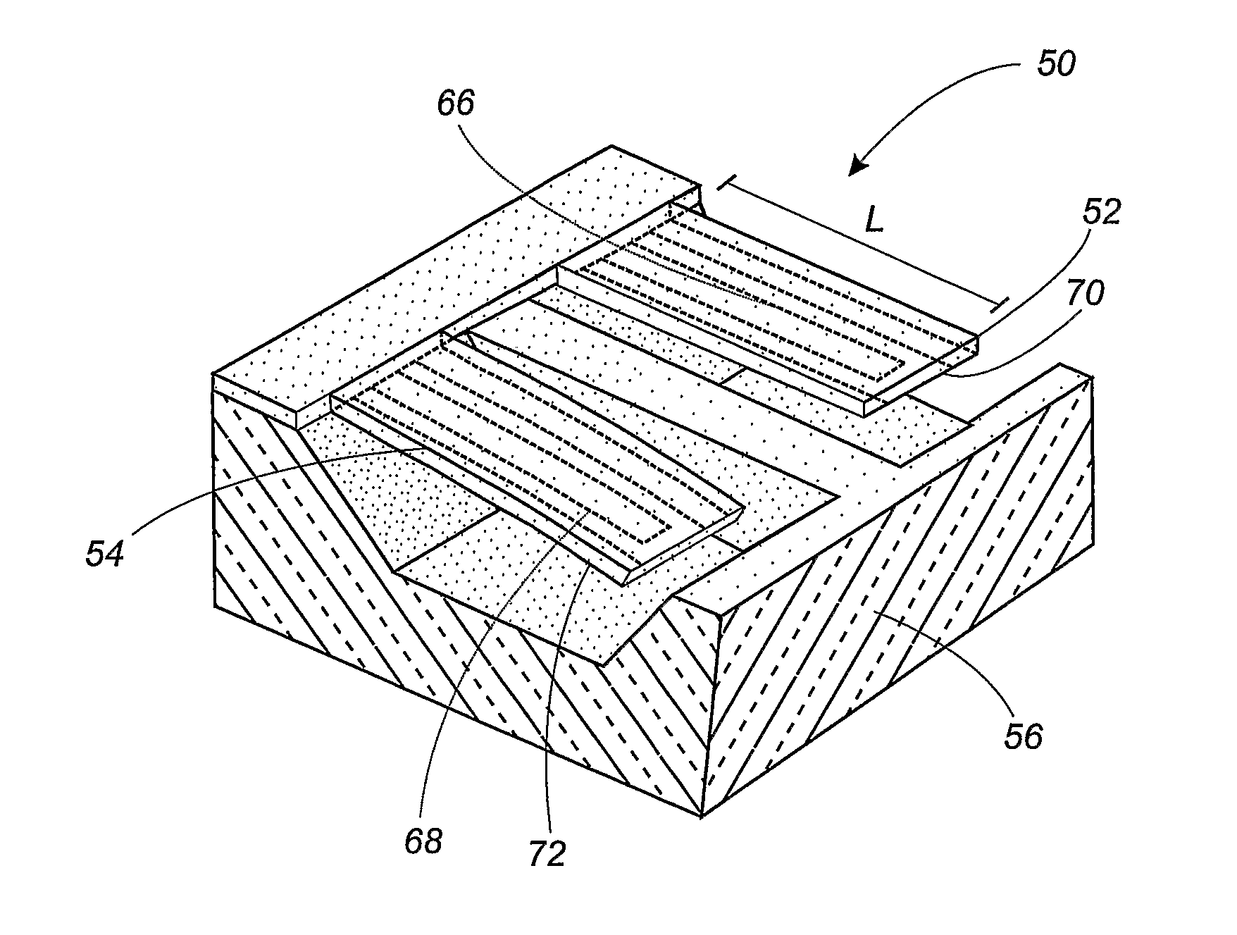
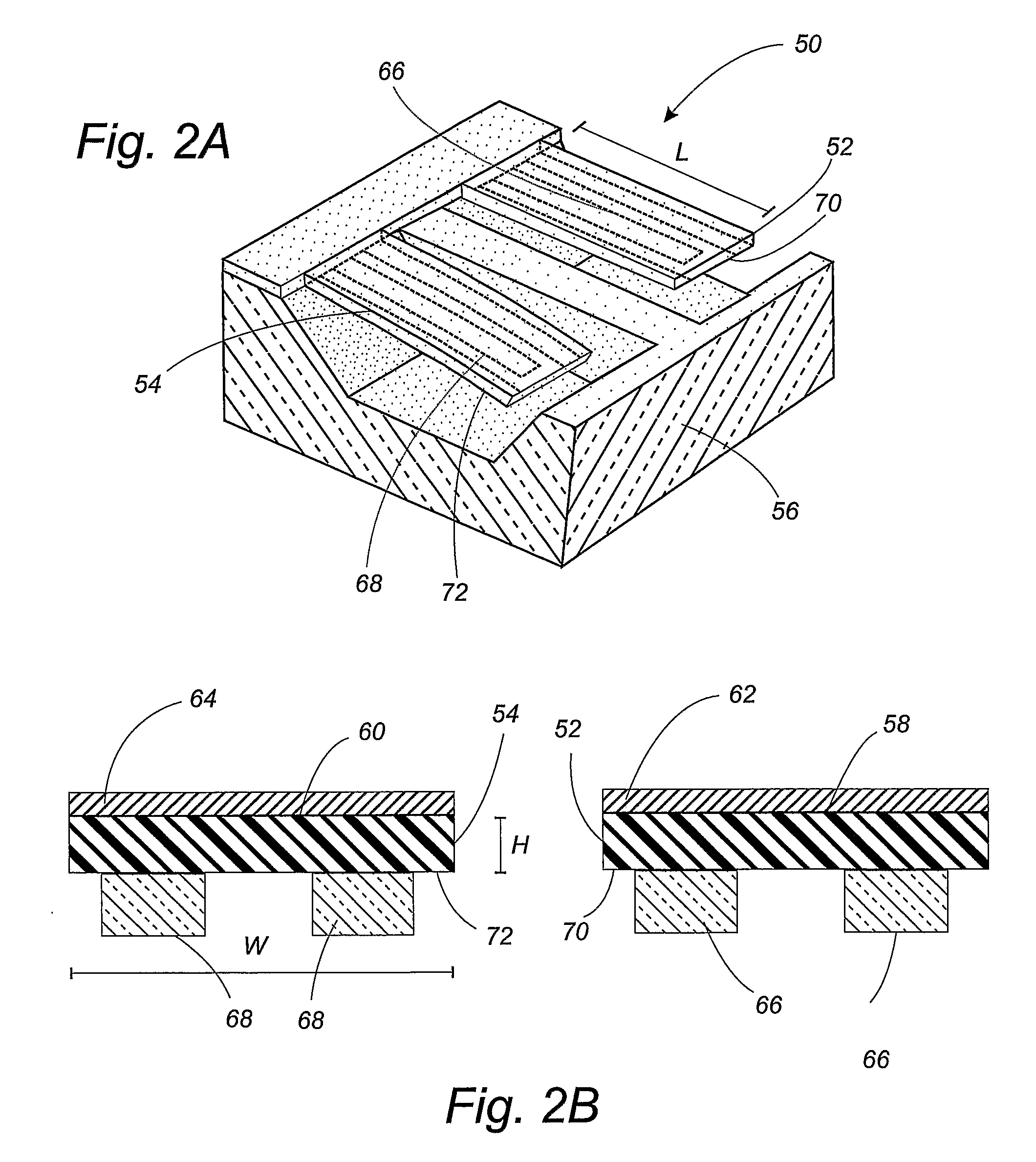
[0023]With reference to FIGS. 2A and 2B, schematics of the piezoresistive cantilevers of the present invention are provided. Cantilever sensor 50 includes cantilever spring elements 52, 54 attached to supporting substrate 56. In some variations of the invention, supporting substrate 56 is a semiconductor wafer. Disposed over first sides 58, 60 of the cantilever spring elements 52, 54 are probe layers 62, 64. In order to act as sensors these probe layers will incorporate a suitable probe material that comprises a plurality of probe molecules or sites that bind to target molecules. Examples of biomolecular bindings that are used by the probe material include DNA hybridization, DNA-RNA binding, antigen-antibody binding, protein-ligand binding, and DNA-protein binding. Mor...


PUM


Abstract

A microcantilever sensor includes a supporting substrate, a cantilever spring element at least partially disposed over the support substrate, a probe layer disposed over the first side of the cantilever spring element, and a piezoresistive transducer attached to the second side of the cantilever spring element. The cantilever spring element is characterized by having a first side and a second side and comprising a polymer having a Young's modulus less than about 100 Gpa. Sensing systems that incorporate the cantilever sensor of the invention include a detector in communication with the piezoresistive transducer to provide measurements of surface strain changes in the piezoresistive transducer.

Description

CROSS-REFERENCE TO RELATED APPLICATIONS[0001]This application claims the benefit of U.S. provisional application Ser. No. 60 / 648,173 filed Jan. 28, 2005.BACKGROUND OF THE INVENTION[0002]1. Field of the Invention[0003]The present invention relates to polymer cantilevers that are useful in biosensor applications, and in particular to parylene cantilevers that are useful in such applications.[0004]2. Background Art[0005]Biosensors play a crucial role in disease diagnosis, drug discovery, environment monitoring, prevention of bio-terrorism, and the like. The biosensor usually consists of two parts: a molecular recognition element (receptor coating) and a transducer that converts the recognition event into different physical signals. Various transduction methods, based on thermal, mass, electrochemical and optical phenomena occurring during the biomolecular recognition event, have been implemented for biological sensing.[0006]Recently, biosensors utilizing cantilever bending caused by su...

Claims


Application Information

Patent Timeline
Patent Type & Authority Patents(United States)
IPC IPC(8): G01B5/28
CPCG01N29/036G01N2291/0256
Inventor XU, YONG
Owner WAYNE STATE UNIV
Why Eureka
Try Eureka