
De-entrainment tray for high capacity operation

a high-capacity, entrainment tray technology, applied in the direction of liquid degasification, separation process, combustible gas purification/modification, etc., can solve the problems of re-entrainment of separated liquid, poor performance of known entrainment trays at higher vapor loads, and adversely affecting fractionation and downstream processing

Active Publication Date: 2011-12-27
EXXON RES & ENG CO
View PDF29 Cites 16 Cited by
  • Summary
  • Abstract
  • Description
  • Claims
  • Application Information

AI Technical Summary

Benefits of technology

[0013]Aspects of embodiments of the invention relate to providing a separation device for a fluid stream with vapor and liquid entrained therein that effectively separates the entrained liquid and prevents the separated liquid from being re-entrained in the fluid stream.
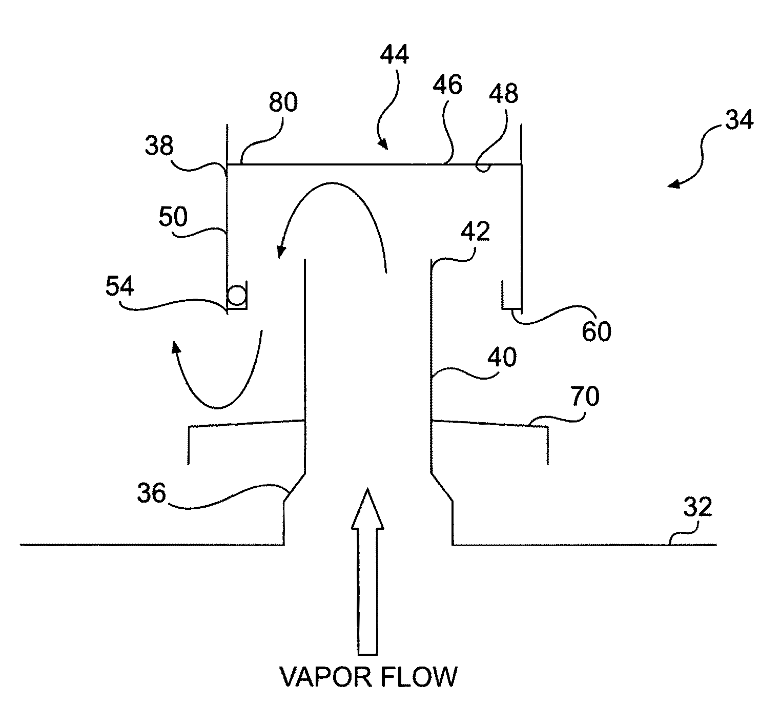
[0015]This invention is directed to a de-entrainment device for separating an entrained liquid from a vapor stream comprising a de-entrainment tray including a tray deck, a plurality of risers extending upwardly through the deck, wherein each riser has a perimeter wall defining a central hollow passage and an outlet, and a plurality of hats. Each hat has a top with an upper surface and a lower surface and a peripheral wall extending downwardly from the top. Each hat is disposed over one riser with the lower surface of the top spaced above its outlet and the peripheral wall surrounding and spaced from the perimeter wall of the riser. An S-shaped vapor flow path extends from below the tray deck, through the passage in the risers, and under the peripheral wall of the hats. Means for preventing re-entrainment of liquid separated from a vapor stream in the vapor flow path is provided.
[0023]The invention also relates to a method of de-entraining liquid from a fluid stream comprising a vapor and entrained liquid flowing from a flash zone in a distillation tower comprising directing the fluid stream through de-entrainment tray positioned above the flash zone, separating the liquid from the vapor in the fluid stream so that the liquid flows to the tray deck and the vapor flows upward in the tower from the hats, and collecting the separated liquid and shielding it from the fluid stream to prevent re-entrainment of the liquid in the vapor flow. The de-entrainment tray has a tray deck with a plurality of risers covered with hats through which the fluid stream flows making an S-turn.

Problems solved by technology

These re-entrained droplets may contain less of the higher boiling components, but their presence in the vapor stream can adversely impact fractionation and downstream processing.
Performance of known de-entrainment trays is poor at higher vapor loads, especially at loads having C-factors of 0.35 ft / s (feet per second or fps) or more.
One problem in conventional devices is that separated liquid can become re-entrained.

Method used


Image

  • De-entrainment tray for high capacity operation
  • De-entrainment tray for high capacity operation
  • De-entrainment tray for high capacity operation

Examples


Embodiment Construction

[0040]The de-entrainment device disclosed herein can be used in various systems that relate to separation devices, particularly devices for separating vapor streams that have entrained liquid droplets. While the device is described in the context of a processing unit in a refinery, especially with respect to crude oil processing, liquid entrainment reduces separation efficiency in other hydrocarbon and non-hydrocarbon systems in which feed entries are flashed. Typical systems include produce strippers or towers that are fed a partially vaporized stream. It will be understood that this device can be used in various settings.

[0041]The de-entrainment device of this application can be embodied as a de-entrainment tray disposed in a separation column, or distillation tower, having a flash zone such that the de-entrainment tray is positioned downstream from and in fluid communication with the flash zone. The separation column, such as a distillation or fractionation tower, can be a vacuum...


PUM

PropertyMeasurementUnit
angleaaaaaaaaaa
diameteraaaaaaaaaa
diameteraaaaaaaaaa

Abstract

A de-entrainment device separates entrained liquid from vapor in a fluid stream that flows through a chimney tray in a distillation tower. The separated liquid is collected and shielded from the fluid stream to prevent re-entrainment of the liquid in the vapor flowing upward into the tower. The chimney tray includes risers with hats that have gutters to guide liquid toward the tray deck, channels to collect and drain liquid from the top of the hats to the tray deck, and baffles extending from the risers to shield the liquid collected on the tray deck from the vapor flow.

Description

CROSS REFERENCE TO RELATED APPLICATIONS[0001]This application relates to and claims priority to U.S. Provisional Patent Application No. 60 / 902,863, entitled “Improved De-Entrainment Tray for High Capacity Operation,” filed on Feb. 23, 2007.BACKGROUND OF THE INVENTION[0002]1. Field of the Invention[0003]This invention relates to devices for separating entrained liquid from vapor. In particular, this invention relates to de-entrainment trays used in distillation towers, especially with respect to hydrocarbon processing.[0004]2. Discussion of Related Art[0005]Separation units, such as atmospheric distillation units, vacuum distillation units and product strippers, are major processing units in a refinery. Atmospheric or vacuum distillation units separate crude oil into fractions according to boiling point so downstream processing units, such as hydrogen treating or reforming units, will have feedstocks that meet particular specifications. Crude oil separation is accomplished by fractio...

Claims


Application Information

Patent Timeline
Patent Type & Authority Patents(United States)
IPC IPC(8): B01D3/06B01D3/20
CPCB01D1/305B01D3/18B01D3/20B01D3/205
Inventor SHARMA, ARUN K.SIDEROPOULOS, THEODORESTOBER, BERNE K.ALBERT, BRIAN D.CHEN, ALVIN U.SINGH, VIKRAM
Owner EXXON RES & ENG CO
Learn More