Eureka AIR delivers breakthrough ideas for toughest innovation challenges, trusted by R&D personnel around the world.

Joined body of dissimilar materials comprising steel material and aluminum material, and joining method therefor

a technology of dissimilar materials and joints, which is applied in the direction of contact member assembly/disassembly, arc welding apparatus, solid-state devices, etc., can solve the problems of high weld strength, and difficult to form reliable joints by using bolts or rivets, etc., to achieve high weld strength and high weld strength

Inactive Publication Date: 2011-05-31
KOBE STEEL LTD
View PDF23 Cites 28 Cited by
  • Summary
  • Abstract
  • Description
  • Claims
  • Application Information

AI Technical Summary

Benefits of technology

[0008]The present invention has been made to solve those problems and it is therefore an object of the present invention to provide a steel-aluminum welded material having high weld strength and capable of being made by spot welding without using any additional materials, such as a clad plate, and without requiring additional processes and to provide a spot welding method for fabricating the steel-aluminum welded material. Another object of the present invention is to provide a steel-aluminum welded material having joints having high weld strength and capable of being stably formed in satisfactory repeatability without causing troubles, such as increase in the reduction of the thickness of the aluminum material, by spot welding and to provide a spot welding method for fabricating the steel-aluminum welded material. A third object of the present invention is to provide a spot welding method that will not cause the cracking of nuggets.Means for Solving the Problem
[0010]Generally, welding together materials of the same quality, such as steel material or aluminum material, by high weld strength by spot welding can be achieved by promoting the formation of nuggets. It is known that the larger the area of nuggets, the higher both the tensile shear strength and the cross tensile strength of the welded material. The area of a nugget is dependent on heat input; the area of a nugget is larger when heat input is larger or weld time is longer. Therefore, a welded material having high weld strength is obtained, in general, by adjusting the diameter of a nugget through the control of heat input during spot welding. It is important to form a nugget having a proper area because the material is melted to its surface and splash occurs if a nugget having an excessively large area is formed.
[0013]A nugget of a large area can be formed and the occurrence of splash can be suppressed when a high welding current is supplied for a short time. Such a welding mode can suppress the melting of the steel material in the interface and can reduce the thickness of the interface reaction layer and can enhance weld strength. Although a nugget of a large area can be formed, the reduction of the thickness of the aluminum material increases due to splash if welding is continued for a long time. Moreover, the steel material is melted greatly in the interface, a thick interface reaction layer is formed and hence weld strength is low.
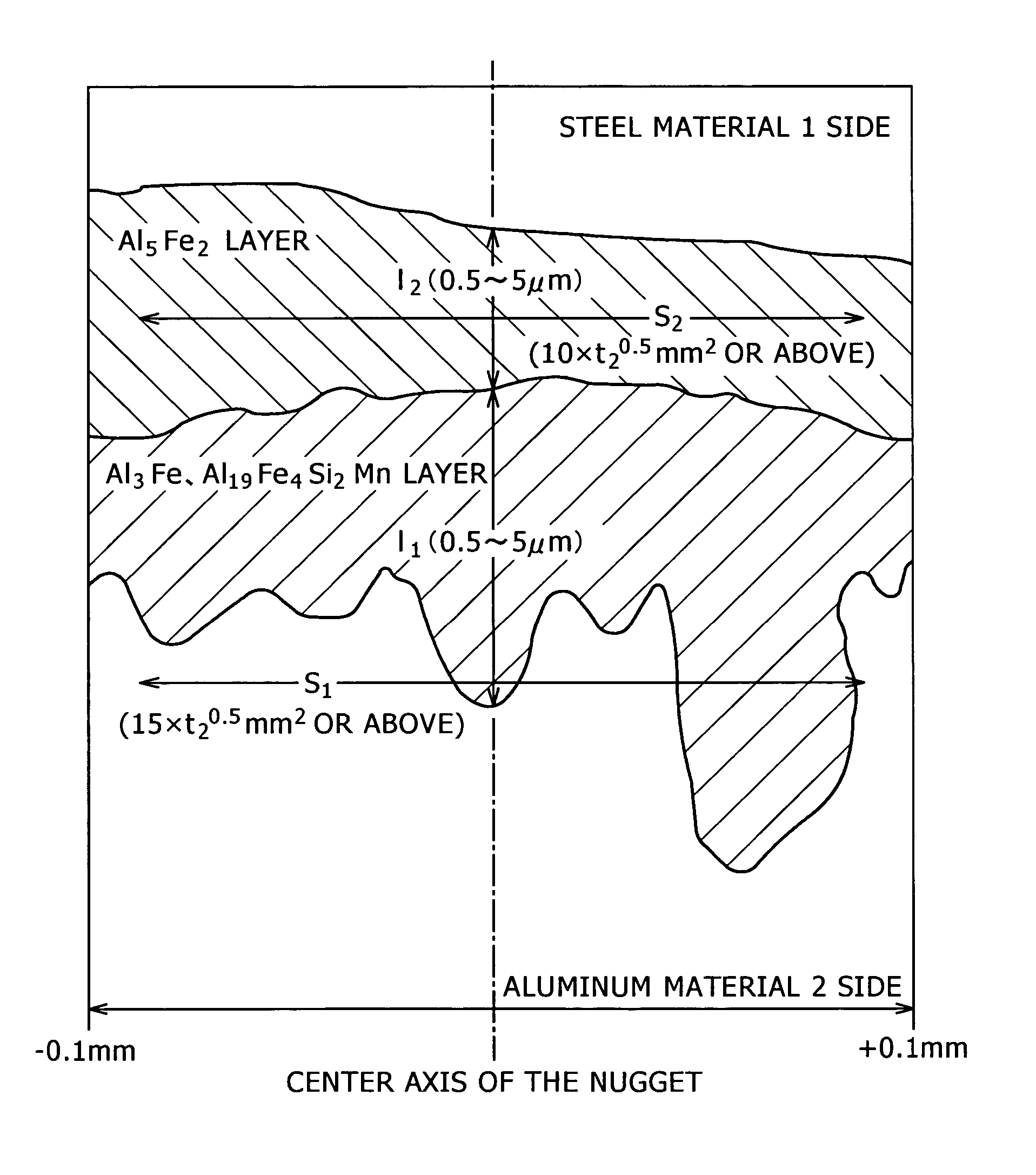
[0017]More concretely, it was found that the weld strength can be greatly enhanced when the thickness of the compound layer of Al3Fe and Al19Fe4Si2Mn on the side of the aluminum material relative to the compound layer of Al5Fe2 is adjusted so as to be in an optimum thickness range and the compound layer of Al3Fe and Al19Fe4Si2Mn of a thickness in the optimum thickness range is formed in a large area.

Problems solved by technology

A brittle intermetallic compound is likely to be produced in the joint of a steel material and an aluminum material when the steel and the aluminum material are welded together and consequently, it has been very difficult to form a reliable, very strong joint, namely, a joint having high weld strength.
However, joints formed by using bolts or rivets have problems in reliability, air tightness and cost.

Method used


Image

  • Joined body of dissimilar materials comprising steel material and aluminum material, and joining method therefor
  • Joined body of dissimilar materials comprising steel material and aluminum material, and joining method therefor
  • Joined body of dissimilar materials comprising steel material and aluminum material, and joining method therefor

Examples


example 1

[0246]A test steel having a chemical composition (% by mass) shown in Table 1 was melted. A slab of the test steel was rolled to obtain a 1.2 mm thick steel material. The steel material was annealed by a continuous annealing process using temperatures between 500° C. and 1000° C. The annealed steel material was cleaned by water washing or oil washing. The cleaned steel material was tempered to obtain a grade 980 MPa high tensile strength steel material. Commercially available aluminum alloy sheets respectively of 0.1 mm and 1.6 mm in thickness of A6022 (type 6000) were used as test aluminum materials.

[0247]The steel material and the aluminum alloy sheets were cut into pieces of the shape of a cross tensile test specimen and the pieces of the steel material and the aluminum alloy sheets were welded together by spot welding to obtain steel-aluminum welded materials. A dc resistance welding tester was used for spot welding. Welding pressures, welding currents and welding times were det...

example 2

[0259]A test steel having a chemical composition (% by mass) shown in Table 1 was melted. A slab of the test steel was rolled to obtain a 1.2 mm thick steel material. The steel material was annealed by a continuous annealing process using temperatures between 500° C. and 1000° C. The annealed steel material was cleaned by water washing or oil washing. The cleaned steel material was tempered to obtain a grade 980 MPa high tensile strength steel material. Commercially available aluminum alloy sheets respectively of 0.1 mm (Tables 10, 11 and 12) and 1.6 mm (Table 12) in thickness of A6022 (type 6000) were used as test aluminum material. The steel sheets (steel materials) and the aluminum alloy sheets (aluminum materials) were cut into pieces of the shape of a cross tensile test specimen specified in A3137, JIS, and the pieces of the steel material and the aluminum alloy sheets were welded together by spot welding under welding conditions shown in Table 9 to obtain steel-aluminum welded...

example 3

[0270]A test steel having chemical compositions (% by mass) shown in Table 14 was melted. A slab of the test steel was rolled to obtain a 1.2 mm thick steel material. The steel material was annealed by a continuous annealing process using temperatures between 800° C. and 900° C. The annealed steel material was cleaned by water washing or oil washing. The cleaned steel material was tempered to adjust the strength of the steel material to a desired strength. A commercially available 1 mm thick A1050 aluminum alloy sheet containing 0.05% Si and not containing Mn and a commercially available 1 mm thick A6022 aluminum alloy sheet containing 1.10% Si and 0.07% Mn were used as test aluminum materials. The steel sheets (steel materials) and the aluminum alloy sheets (aluminum materials) were cut into pieces of the shape of a cross tensile test specimen specified in A3137, JIS, and the pieces of the steel sheets and the aluminum alloy sheets were welded together by spot welding to obtain ste...


PUM

PropertyMeasurementUnit
thicknessaaaaaaaaaa
thicknessaaaaaaaaaa
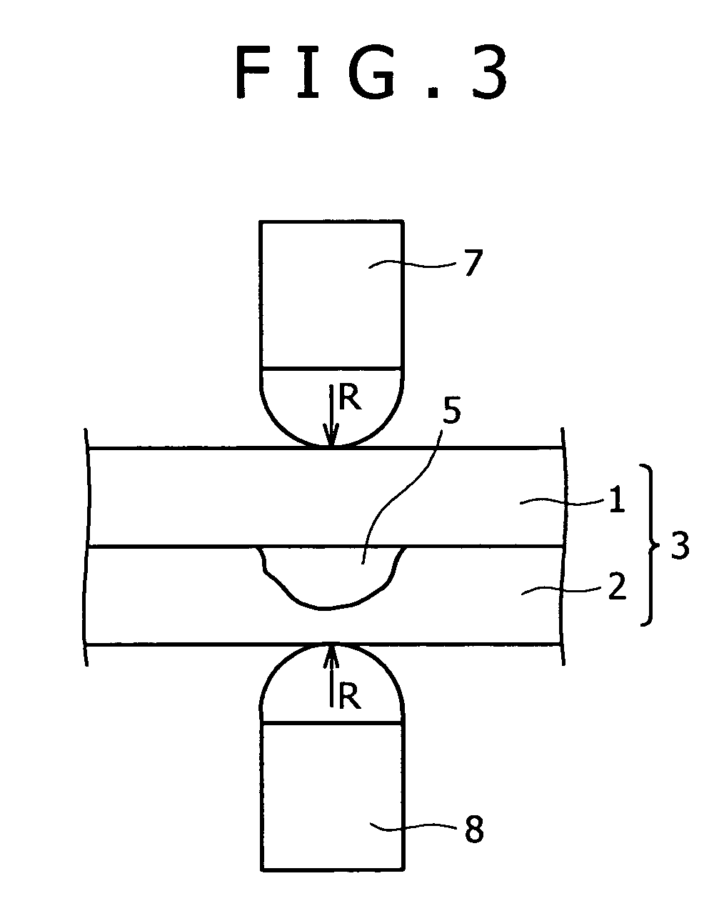
thicknessaaaaaaaaaa

Abstract

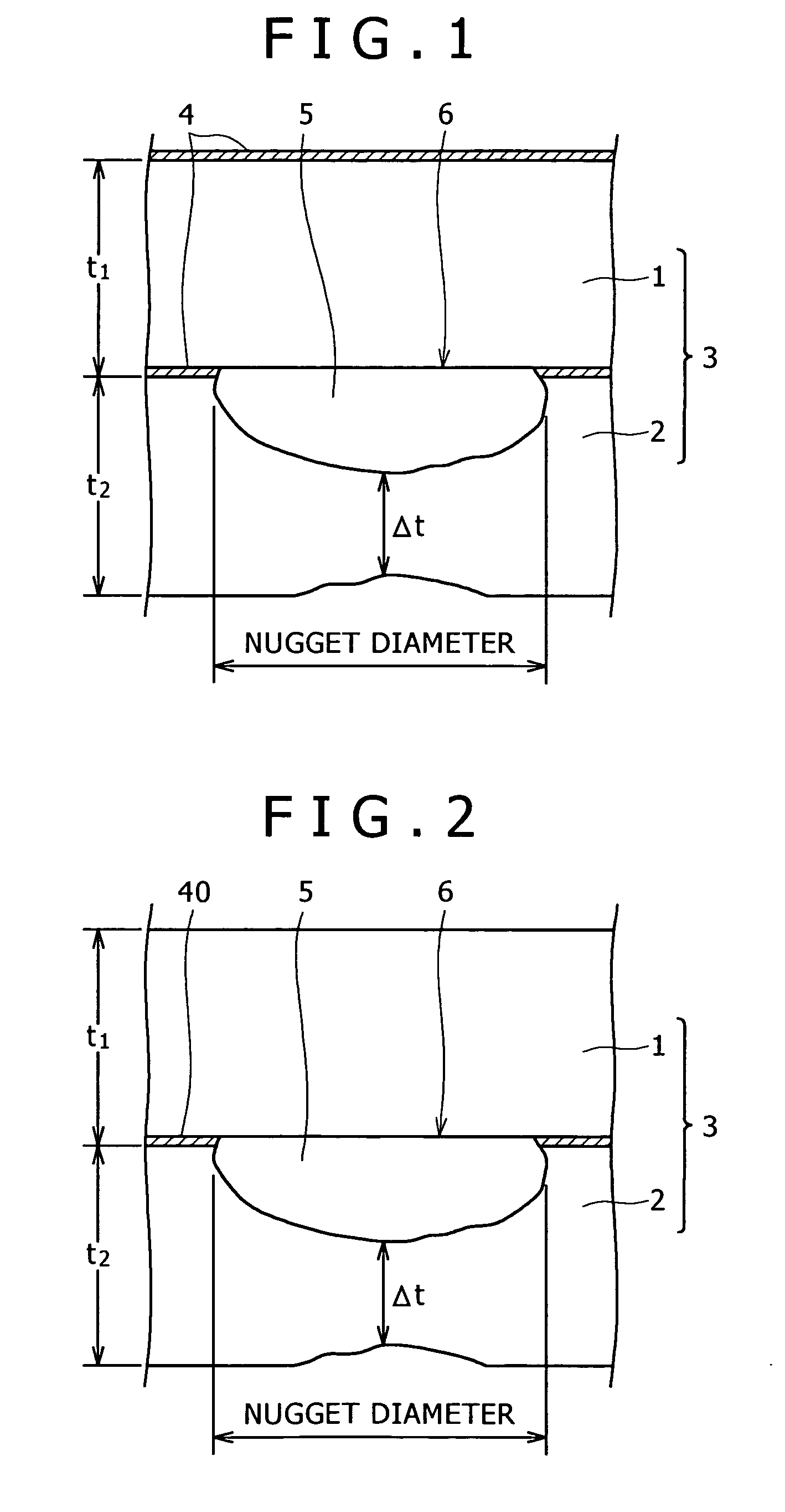
To provide a steel-aluminum welded material and a spot welding method therefor having high weld strength.The steel-aluminum welded material 3 includes a steel material 1 and an aluminum material 2 having predetermined widths. The area of a nugget 5 of a spot-welded part is determined as a function of the thickness of the aluminum material 2, and the area of a part of the nugget 5 corresponding to a part having a thickness in a range between 0.5 and 10 μm of an interface reaction layer 6 is defined as a function of the thickness of the aluminum material 2.

Description

TECHNICAL FIELD[0001]The present invention relates to a steel-aluminum welded material formed by welding together a steel material and an aluminum material for making parts of transport equipment including automobiles and rolling stock, machine parts and architectural structures, and a steel-aluminum welded material fabricating method.BACKGROUND ART[0002]Generally, spot welding is used for welding together members of the same metal. Spot welding will contribute greatly to weight reduction of material, provided that members respectively of different metals, such as an aluminum member and an iron-base member can be welded together by spot welding. The term “aluminum” is used for designating pure aluminum and aluminum alloys, and the term “steel” will be used instead of “iron-base” in this specification.[0003]A brittle intermetallic compound is likely to be produced in the joint of a steel material and an aluminum material when the steel and the aluminum material are welded together an...

Claims


Application Information

Patent Timeline
Patent Type & Authority Patents(United States)
IPC IPC(8): B32B7/04B32B15/18B32B15/20B23K9/007B23K11/20
CPCB23K11/20B23K2203/20Y10T428/12951Y10T428/12229Y10T428/12757Y10T428/12194B23K2103/20B23K11/11B23K11/241B23K2101/18
Inventor URUSHIHARA, WATARUTAKEDA, MIKAKOMATSUMOTO, KATSUSHIKATOH, JUNSUGIZAKI, YASUAKIIDO, HIDEKAZU
Owner KOBE STEEL LTD
Why Eureka
Eureka Blog
Learn More