Controllable power supply circuit for an illumination system and methods of operation thereof

a power supply circuit and controllable technology, applied in the direction of electric variable regulation, process and machine control, instruments, etc., can solve the problems of affecting the functioning of the whole dimmer-inverter system, instability of switching moment, lack of dimmer load, etc., and achieve the effect of increasing the duration of said voltage slices

Inactive Publication Date: 2010-12-21
LIGHTECH ELECTRONICS INDS
View PDF12 Cites 8 Cited by
  • Summary
  • Abstract
  • Description
  • Claims
  • Application Information

AI Technical Summary

Benefits of technology

[0023]This object is realized in accordance with a first aspect of the invention by a method for reducing acoustic noise produced during use of a lamp leading edge dimmer, the method comprising:
[0039](b) increasing the duration of said voltage slices during successive AC half cycles while ensuring that a filament current flowing through a filament of the lamp does not exceed a predetermined threshold prior to ignition of the filament lamp.

Problems solved by technology

This leads to the absence of a load on the dimmer, which is a drawback of this dimmer-inverter system.
Additional drawbacks relate to the instability of the switching moment relative to the zero crossing of the input voltage, which depends on the inverter load, length of connecting wires, capacitance of the input filter, capacitance in the inverter's input bridge, etc.
Moreover, as is explained below in greater detail, the presence of the passive state of the inverter prior to ignition causes a number of parasitic processes which desynchronize the inverter and destroy the normal functioning of the dimmer, which in turn harm the functioning of the whole dimmer-inverter system.
It is also known that the presence of sharp current fronts in operation of the dimmer is one of the causes of mechanical vibration of the lamp, which leads to acoustic noise.
In the latter case, during the cut-off of the backward front there arises an additional current in the capacitor during the time of its discharge which leads to large mechanical vibration of the capacitor which again causes acoustic noise.
An additional drawback of the dimmer inverter system is the fact that the inverter must be designed to work either with the leading edge dimmer or the trailing dimmer, or must be provided with a circuit that is able to determine the dimmer type and can change its operation accordingly.
However, if the dimmer type is determined incorrectly, very high acoustic noise and large shocks can arise in inverter circuits.
For instance, it may happen that the leading edge dimmer will function without the shaping of the forward front with a large capacitance in the input bridge, which will lead to additional currents in the inverter and dimmer and large vibration and acoustic noise of the capacitor.
During the inactive part of the period, i.e. when the inverter is not conductive, the capacitor 40 is charged and causes ignition to be late and unstable.
This may cause several undesired scenarios:The inverter may cause early ignition of the dimmer and change its ignition angle;By the time the dimmer ignites, the inverter switches off, not having enough energy to sustain normal operation.
Owing to the required latency, it will re-ignite late;The early ignition of the inverter, having a nature of a fluctuation, may cause a spike in the output of the dimmer which may in turn lead to another unwanted re-ignition of the inverter.
All these processes, being dependent on a multitude of external parameters such as ignition angle, inverter load, ambient conditions, etc. will lead to unstable operation of the system, when a dimmer is connected, in one of the described modes.
This leads to a loss of load on the dimmer, which is undesirable since it created flickering at the lamp and it enhances dimmer noise.
These shock currents reduce expected life of the lamp.
Furthermore, so far as power supplies that operate with dimmers are concerned, there remains the problem of acoustic noise whose reduction is amenable to further improvement; and the discontinuous ignition of the inverter and resulting instability of the inverter-dimmer-load system calls for improvement.

Method used


Image

  • Controllable power supply circuit for an illumination system and methods of operation thereof
  • Controllable power supply circuit for an illumination system and methods of operation thereof
  • Controllable power supply circuit for an illumination system and methods of operation thereof

Examples


Embodiment Construction

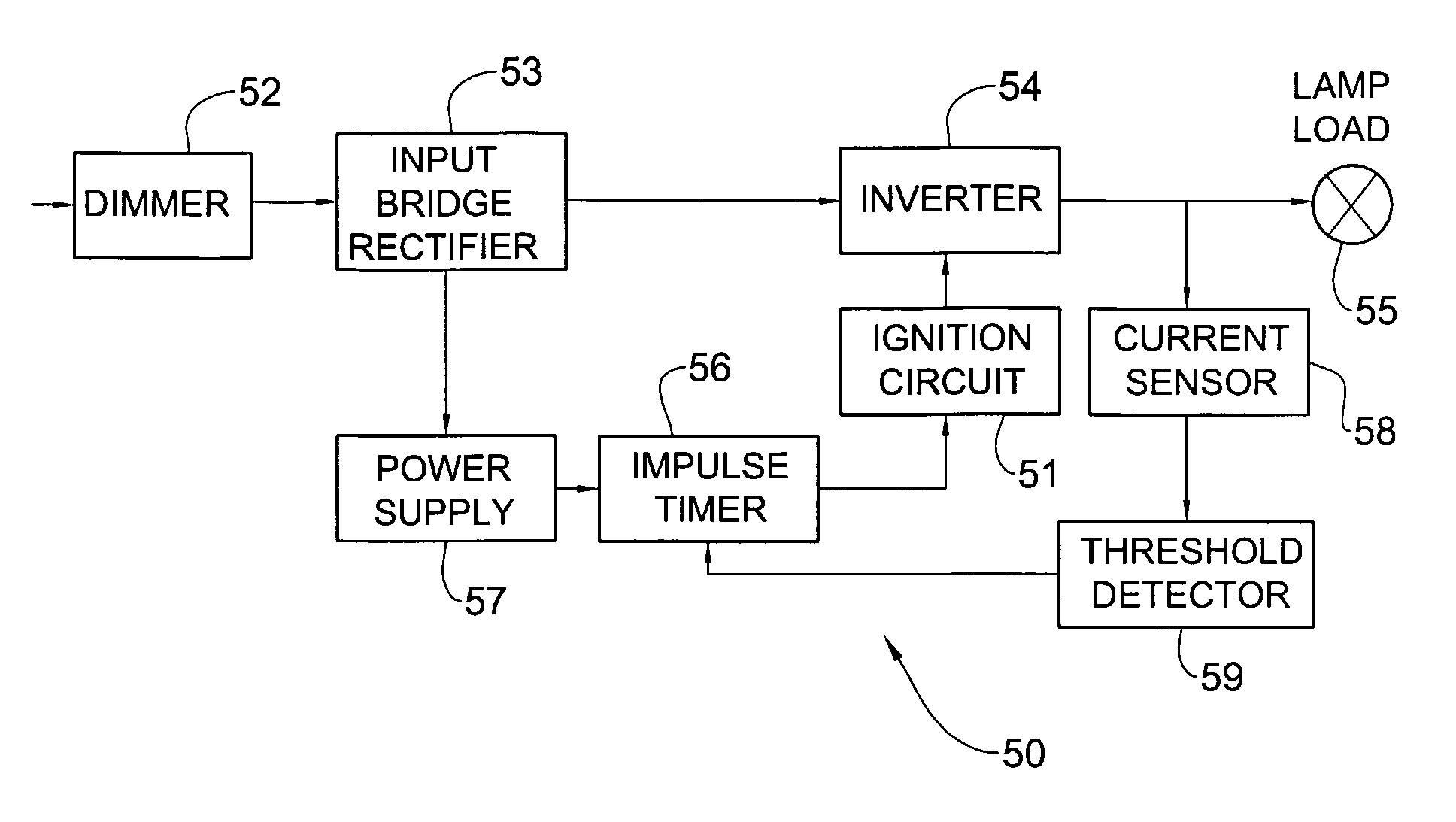
[0063]FIG. 5 is a block diagram showing functionally a variable power supply circuit according to the invention shown generally as 50 having an improved inverter ignition circuit 51 for use with a current feedback inverter. Regardless of the application for which the inverter is required, such an inverter must be ignited by an ignition pulse. The power supply 50 comprises a dimmer 52 coupled to the input of an input bridge rectifier 53, whose output is coupled to an inverter 54 in known manner for producing an output voltage that is fed to a lamp 55. The ignition circuit 51 is controlled by an impulse timer 56 energized by an energy accumulator circuit 57 and responsively coupled to a current sensor 58 and threshold detector 59.

[0064]FIG. 6a is a circuit diagram showing schematically a detail of the inverter ignition circuit 51 illustrated in FIG. 5. The inverter comprises a bridge of four bipolar NPN junction transistors 61, 62, 63 and 64. The collectors of the transistors 61 and 6...


PUM


Abstract

A method for reducing acoustic noise produced during use of a lamp dimmer detects whether the dimmer is a leading edge (101) or a trailing edge dimmer (102). A nominal firing time of a leading edge dimmer is determined and a post-correction applied to a voltage applied to the dimmer starting from the nominal firing time so as to build-up the voltage gradually during a predetermined post-correction time period and thereby reduce the rate of rise of the leading edge thereof. A nominal cutoff time of a trailing edge dimmer is determined and a pre-correction applied to a voltage applied to the dimmer starting from the nominal cut-off time so as to diminish the voltage gradually during a predetermined pre-correction time period and thereby reduce the rate of rise of the leading edge thereof. Other methods are disclosed for soft starting filament lamps and controlling dimmer circuits.

Description

FIELD OF THE INVENTION[0001]This invention relates to power supplies for low voltage lighting systems.BACKGROUND OF THE INVENTION[0002]Power supplies for lighting systems typically comprise a rectifier inverter system for converting an incoming mains voltage to a high frequency.[0003]FIG. 1 shows a low voltage illumination system designated generally as 10 as described in U.S. Pat. No. 6,097,158 (Manor et al.) commonly assigned to the present assignee and incorporated herein by reference. The illumination system 10 comprises a pair of input terminals 11 and 12 for connecting to a source of low frequency AC voltage 13 shown in dotted outline. The AC voltage source 13 is derived from a conventional electricity supply feeder having a typical mains voltage of 347-100 V and a supply frequency of 50 / 60 Hz. A conventional rectifier 14 is coupled via the terminals 11 and 12 to the source of AC voltage 13 for converting the low frequency AC voltage to DC which is then fed to an inverter 15 c...

Claims


Application Information

Patent Timeline
Patent Type & Authority Patents(United States)
IPC IPC(8): H05B37/00H02M5/293H05B39/02H05B39/04H05B39/08
CPCH05B39/02Y10S315/04
Inventor TSINKER, VICTORFIRTEL, ALEXANDER
Owner LIGHTECH ELECTRONICS INDS
Why Eureka
Try Eureka