
Remote biological, chemical and explosive detector

a biological, chemical and explosive agent technology, applied in the field of detection devices and methods, can solve the problems of inability to fully protect a large area, delay can have severe consequences, and the manual detection process is highly intrusive, so as to achieve effective alerts, reduce the effect of invasiveness and rapid deployment and operation

Inactive Publication Date: 2010-11-16
AVAAK
View PDF7 Cites 21 Cited by
  • Summary
  • Abstract
  • Description
  • Claims
  • Application Information

AI Technical Summary

Benefits of technology

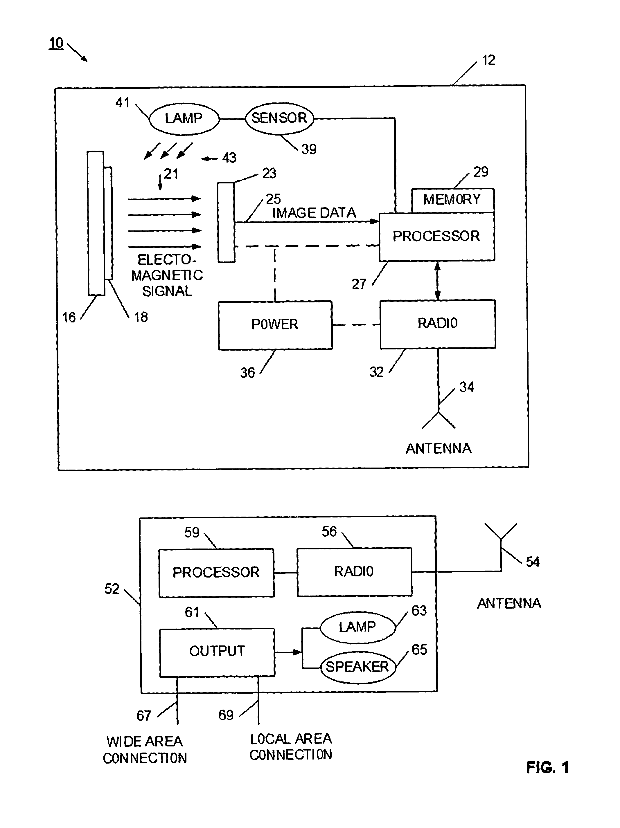
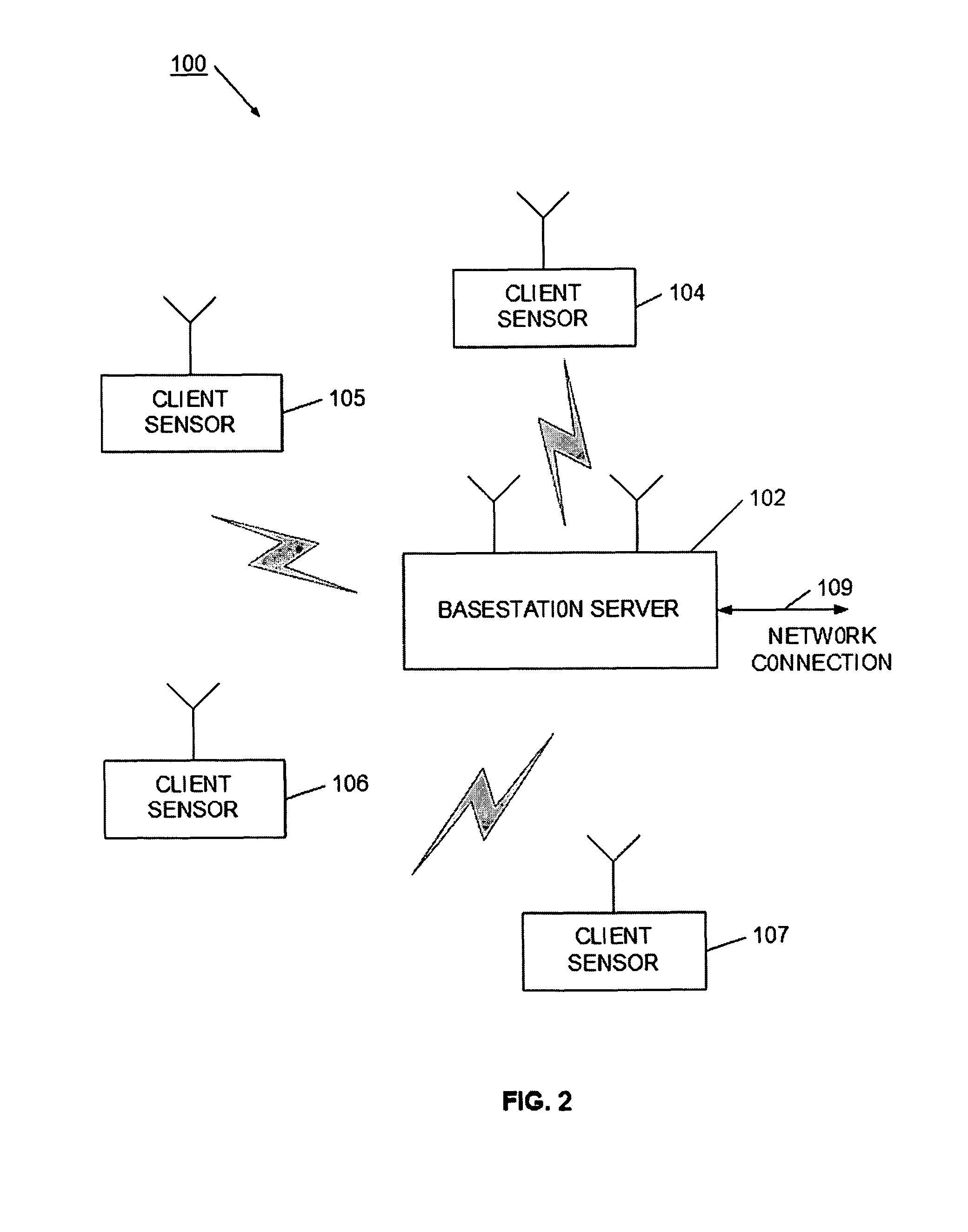
"The present invention provides a distributed detector system for remotely detecting agents indicating the presence of particular biological, explosive, or chemical targets. The system consists of a central server or base station wirelessly communicating with a set of distributed detectors. Each detector has a reactive material that changes an optical property in the presence of a target agent. A camera is positioned to take images of the reactive material from time to time, and has local processing to determine when the reactive material has likely changed. The detector wirelessly communicates to the central server or base station, and appropriate alerts or notifications can be generated. The detector system allows for a robust detection system that is minimally invasive on the local environment, does not require installing expensive data and power lines, but yet generates effective alerts as to the presence of biological, chemical, or explosive agents. The detection system may be quickly deployed and operational, and with the small size and low cost of the individual detectors, allows for dense detector presence in an area. Also, the detector may be configured to detect multiple agents, or may be readily fitted with a different reactive material when a different target agent is selected. The detection system may therefore be a highly effective monitoring system for public transportation systems, buildings, events, airports, or battle zone areas. The detection system is noninvasive, autonomous, and can operate unattended for long periods."

Problems solved by technology

However, such a manual detection process is highly intrusive, as it requires the presence of security and monitoring personnel at the risk site, and, it is not possible to fully protect a large area over extended periods due to staffing limitations.
Since reaction time is critical in many threat situations, such a delay can have severe consequences.
Also, since each detector is expensive, the overall cost of protecting an area is quite high, and limits the density of protection in all but the most critical areas.
Unfortunately, in today's world, almost every building, event, and transportation system is a potential target of attack.
With the cost and difficulty of installing these permanent systems, very few potential targets are actually being monitored.
Also, the permanently installed systems are ineffective or uneconomical for temporary events.
Although the hotel may benefit from an installed detection system, it is not economically feasible to install a full threat detection system to support threat detection for just one speech.
Therefore, such events are typically monitored by security personnel, which detracts from and interferes with the event.
And, as described above, human monitoring may provide a threat response that is too slow to be effective.
For example, manufacturing threats, such as gas leaks, biological agent release, and chemical spills pose a threat to workers as well as to the surrounding area.
In another example, environmental threats, such as air pollution, water contamination, and the use of illegal pesticides and herbicides present vast areas that are currently difficult to monitor.
Due to the cost of the medical assaying devices, and the sophistication needed to operate them, such devices are not readily available in these areas.

Method used


Image

  • Remote biological, chemical and explosive detector
  • Remote biological, chemical and explosive detector
  • Remote biological, chemical and explosive detector

Examples


Embodiment Construction

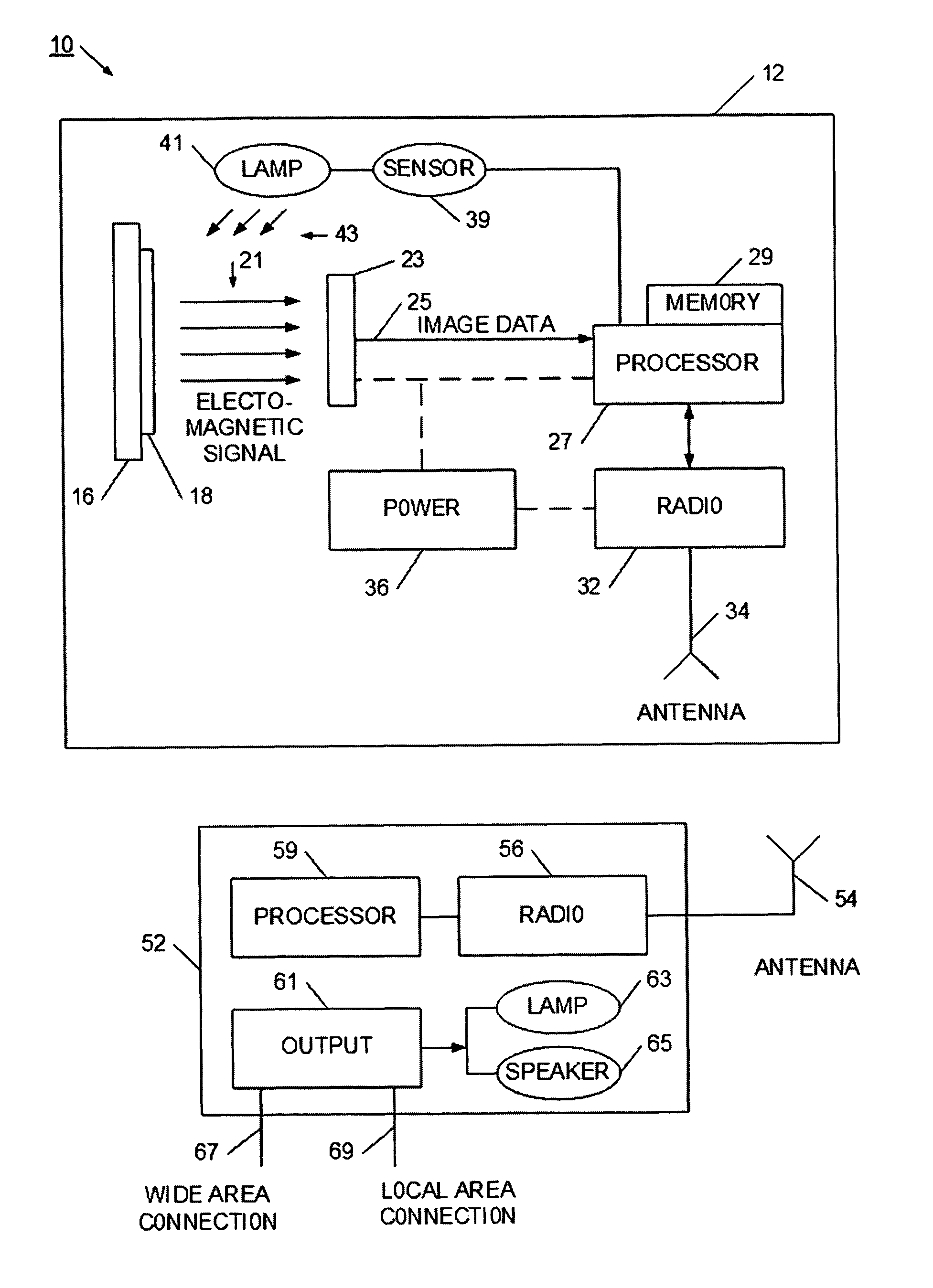
[0017]Referring now to FIG. 1, an autonomous sensing system 10 is illustrated. Sensing system 10 enables a remote detector 12 to automatically and autonomously detect a target agent. For example, the detector 12 may be set to detect particular biological, chemical, explosive, or other target agents. When the target agent is detected, the detector 12 may send an alert to a base station 52. In this way, a remote detector is able to autonomously provide information regarding the presence of a target agent. Also, the detector 12 has sufficient intelligence and processing power to determine when the agent is present and to classify the threat or urgency the agent presents. For example, the detector may be set to detect the presence of a toxic gas. In the presence of the gas, the detector will be able to alert that the toxic gas is present, as well as classify its concentration to set the urgency or threat level. In this way, a much more urgent alert may be transmitted to the base station...


PUM

PropertyMeasurementUnit
optical propertyaaaaaaaaaa
frequencyaaaaaaaaaa
radio frequencyaaaaaaaaaa

Abstract

A distributed detector system is provided for remotely detecting agents indicating the presence of particular biological, explosive, or chemical targets. The distributed detector system may be used for security threat detection, manufacturing or environmental monitoring, or medical assaying. In the detection system, a central server or base station wirelessly communicates with a set of distributed detectors. In this way, the central server or base station is able to aggregate detection information, as well as apply additional processing and analysis to data collected at the detectors. Each detector has a reactive material, such as a silicon-polymer, that changes an optical property in the presence of a target agent. A camera is positioned to take images of the reactive material from time to time, and has local processing to determine when the reactive material has likely changed. In some cases, the detector may have sufficient processing power to classify the change according to its urgency or threat level. The detector wirelessly communications to the central server or base station, and appropriate alerts or notifications can be generated.

Description

RELATED APPLICATIONS[0001]This application claims priority to U.S. provisional patent application No. 60 / 633,032, filed Dec. 6, 2004, and entitled “Autonomous Remote Biological, Chemical, and Explosive Detector Using Color Imaging Analysis”, which is incorporated herein in its entirety.FIELD OF THE INVENTION[0002]The field of the present invention is detection devices and methods. More particularly, a device and system is disclosed for remotely detecting biological, chemical, and explosive agents.BACKGROUND[0003]Since the events of Sep. 11, 2001, the world, and in particular the US, has become more aware of the need to monitor and detect terror, chemical, biological, and explosive threats. Typically, detection has either been a manual process, or has required a substantial installation process. For the manual process, people with detectors are positioned or rove in high risk areas to monitor for target threat agents. These agents are typically released or accompany known chemical, b...

Claims


Application Information

Patent Timeline
Patent Type & Authority Patents(United States)
IPC IPC(8): G01T1/24G01N21/00C12Q1/68
CPCG01N21/78G01N31/224G01N21/31G01N21/783G01N2021/7786
Inventor GOLDBERG, BAR-GIORAMESSINGER, GIOIA
Owner AVAAK
Learn More