Control apparatus for electric vehicles

a technology for controlling apparatus and electric vehicles, applied in the direction of dc-ac conversion without reversal, electric energy management, electric devices, etc., can solve the problems of voltage appearing on the power supply line becoming excessively high, voltage variations, etc., and achieves stable voltage appearance, low cost, and small size

Active Publication Date: 2010-10-05
DENSO CORP
View PDF8 Cites 3 Cited by
  • Summary
  • Abstract
  • Description
  • Claims
  • Application Information

AI Technical Summary

Benefits of technology

[0009]It is thus an object of the present invention to improve a control apparatus for electric vehicles to be capable of stabilizing a voltage appearing on a power supply line in small size and low cost and to be capable of reducing a torque variation to nearly zero in a transient condition of controlling an input power to a motor unit.
[0010]According to one aspect, a control apparatus for an electric vehicle comprises a conversion unit that converts a voltage supplied by a DC power supply into a system voltage appearing on a power supply line, and an MG unit that includes an inverter connected to the power supply line and drives an AC motor. The control apparatus controls a torque of the AC motor and an input electric power to the MG unit independently from each other, executes a system voltage stabilization control to control an electric power input to the MG unit so as to suppress variation in the system voltage by sending a command value for controlling the input electric power, executes a conversion power control to control a conversion power, which is an input electric power or an output electric power, executes a conversion voltage control to control the voltage output, selects an execution of either the conversion power control or the conversion voltage control, and inhibits execution of the system voltage stabilization control when the conversion voltage control is selected. The control apparatus further reduces a difference between the first estimated torque and the second estimated torque to zero substantially so that a torque of the MG unit is restricted from varying in a transient condition of controlling an input power of the MG unit, by calculating a first estimated torque of the AC motor based on a current flowing in the AC motor and calculating a second estimated torque of the AC motor based on a current related to torque control of the AC motor.

Problems solved by technology

When a relation between electric power driving one of the AC motors and electric power generated by the other AC motor considerably varies due to a change in vehicle operating state or another reason, however, voltage variations caused by a change in such relation as voltage variations of the power supply line cannot be absorbed by the voltage boosting converter and / or the smoothing capacitor.
Thus, the voltage appearing on the power supply line becomes excessively high.
As a result, it is likely that electronic equipment connected to the power supply line is damaged.
By adoption of this method, however, the voltage boosting converter with better performance and the smoothing capacitor with a larger capacitance will inevitably raise the cost of the control apparatus for an electric vehicle.
Thus, demands for a system having a small size and a low cost cannot be met.
In addition, even if an attempt is made to control the inverter to make the sum of energies (or the balance of power) of the two AC motors equal to 0 in a normal state, it is difficult to control the inverter to make the sum of energies (or the balance of power) of the two AC motors equal to 0 in the following cases.
The AC motor linked to the internal combustion engine is not capable of obviating power variations caused by changes of a torque generated by the internal combustion engine.
This fact makes it even more difficult to control the inverter to make the sum of energies of the two AC motors equal to 0.

Method used


Image

  • Control apparatus for electric vehicles
  • Control apparatus for electric vehicles
  • Control apparatus for electric vehicles

Examples


first embodiment

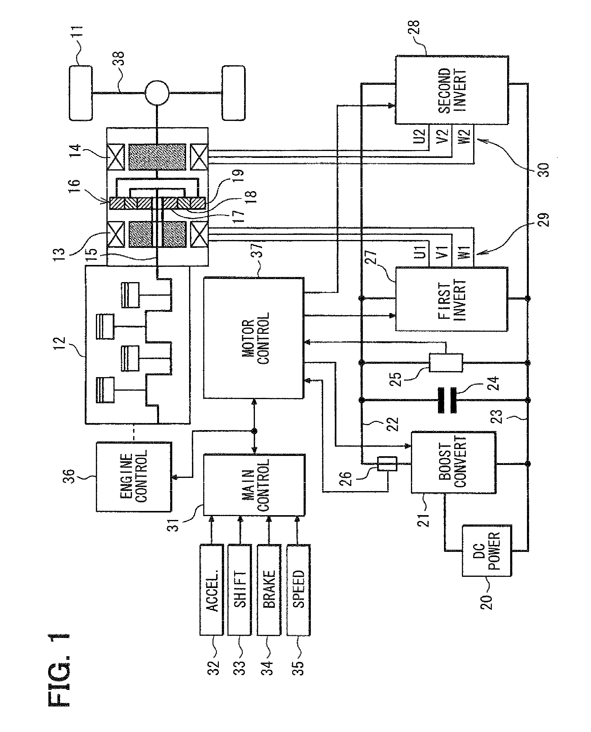
[0023]Referring first to FIG. 1, an electric vehicle 11 has an internal combustion engine 12 in addition to a first AC motor 13 and a second AC motor 14. Thus, the electric vehicle 11 is an engine / motor hybrid vehicle. The engine 12 and the second AC motor 14 are employed as a drive power source for driving the electric vehicle 11. Power generated by a crankshaft 15 of the engine 12 is divided into two paths by a planetary gear set 16. The planetary gear set 16 includes a sun gear 17, a planetary gear 18 and a ring gear 19. The sun gear 17 rotates at its radial center. The planetary gear 18 rotates along a circumference external to the sun gear 17 while revolving around its radial center. The ring gear 19 rotates along a circumference external to the planetary gear 18. The planetary gear 18 is linked to the crankshaft 15 of the engine 12 through a carrier not shown in the figure. On the other hand, the ring gear 19 is linked to a rotation shaft of the second AC motor 14. The sun gea...

second embodiment

[0090]According to a second embodiment, as shown in FIG. 10, a torque difference reduction control unit 93 is provided in place of the torque difference reduction control unit 86 in the first embodiment (FIG. 5). Further, as shown in FIG. 11, the control unit 93 has a second torque estimation unit 94 in place of the second torque estimation unit 88 in the first embodiment (FIG. 8).

[0091]Specifically, the control unit 93 calculates a second estimated torque Tt, which is an estimated torque generated by the second AC motor 14, based on the detection current vector it2 (d-axis detection current idt2, q-axis detection current iqt2) for torque control. The control unit 93 then executes a torque difference reduction control to reduce a torque difference ΔT between the first estimated torque T and the second estimated torque Tt to nearly zero.

[0092]More specifically, the first torque estimation unit 87 estimates the first estimated torque T as follows by using the detected motor current ve...


PUM


Abstract

In a hybrid vehicle control apparatus, a motor control unit executes the input power control on a MG unit independently from a torque control on an AC motor so that the input power control and the torque control are stabilized. The motor control unit further executes a torque difference reduction control, which controls current vector of the AC motor, to reduce a torque difference to zero substantially thereby preventing uncomfortable torque variation in a transient condition of input power control of the MG unit. The torque difference is calculated based on a first estimated torque calculated from a detected motor torque of the AC motor and a second estimated torque calculated from a command current vector for torque control of the AC motor.

Description

CROSS REFERENCE TO RELATED APPLICATION[0001]This application is based on and incorporates herein by reference Japanese Patent Application No. 2006-336627 filed on Dec. 14, 2006.[0002]This application is related to U.S. patent application Ser. No. 11 / 707,903 (IPICS 103382-US) filed on Feb. 20, 2007.FIELD OF THE INVENTION[0003]The present invention relates to a control apparatus for an electric vehicle including a system for converting a voltage generated by a DC power supply into a system voltage by using a voltage converter and for driving an AC motor by applying the system voltage to the AC motor through an inverter.BACKGROUND OF THE INVENTION[0004]As disclosed in documents such as U.S. Pat. No. 7,099,756 (JP 2004-274945A), in an electric vehicle having AC motors mounted therein to serve as a power source of the vehicle, the AC motors are each capable of serving as a motor for driving wheels of the vehicle as well as a motor driven by an engine to generate power. As the above syste...

Claims


Application Information

Patent Timeline
Patent Type & Authority Patents(United States)
IPC IPC(8): H02P7/00B60L3/00B60L9/18H02M3/00H02M7/48H02P21/00H02P21/14H02P21/18H02P21/22H02P21/24H02P23/14H02P25/026H02P27/06H02P27/08
CPCB60K6/445B60L3/0046B60L11/123B60L11/14B60L15/025B60W10/08B60K6/365B60K1/02Y02T10/6239B60L2210/14B60L2210/20B60L2210/40B60L2240/423B60L2270/20B60W20/00Y02T10/6217Y02T10/643Y02T10/7077Y02T10/7225Y02T10/725Y02T10/7241B60L50/61B60L50/16Y02T10/62Y02T10/64Y02T10/72Y02T10/7072Y02T10/70B60W2510/083H02P27/08
Inventor EGAMI, TSUNEYUKI
Owner DENSO CORP
Why Eureka
Try Eureka