
Method of recovering ammonia

a technology of ammonia and ammonia gel, which is applied in the preparation of isocyanic acid derivatives, separation processes, organic chemistry, etc., can solve the problems of severe corrosion and industrially impossible long-term production of distillation apparatuses made of such materials

Active Publication Date: 2010-08-31
MITSUBISHI GAS CHEM CO INC
View PDF10 Cites 1 Cited by
  • Summary
  • Abstract
  • Description
  • Claims
  • Application Information

AI Technical Summary

Benefits of technology

The present invention provides a method for recovering ammonia from an aqueous solution containing ammonia, carbon dioxide, and hydrogen cyanide using a distillation apparatus made of a specific alloy. This method prevents corrosion of the distillation apparatus and allows for long-term production of ammonia. Additionally, the invention provides a method for producing a nitrile compound by allowing a cyclic hydrocarbon or a heterocyclic compound to react with ammonia, separating the nitrile compound from the reaction product gas, and absorbing ammonia, carbon dioxide, and hydrogen cyanide in a remaining gas using water.

Problems solved by technology

It was found that materials such as SUS304 were severely corroded during the distillation, and the long-term production using a distillation apparatus made of such materials is industrially impossible.

Method used


Image

  • Method of recovering ammonia
  • Method of recovering ammonia

Examples


example 1

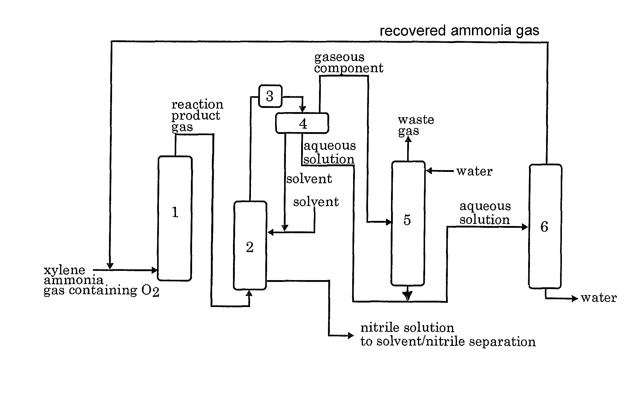
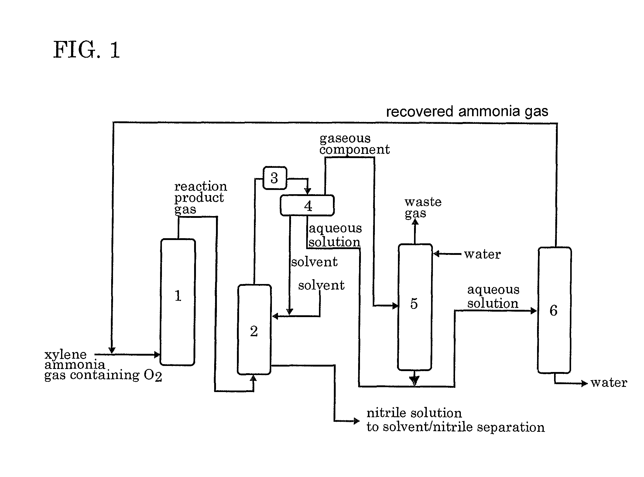
[0045]According to the process flow shown in FIG. 1, the ammoxidation, the separation of the nitrile compound, the contact of the remaining gas with water, and the distillation of the aqueous solution were conducted continuously. In FIG. 1, each reference numeral represents an ammoxidation reactor 1, a nitrile compound absorber 2, a cooler 3, a decanter 4, an ammonia absorber 5 and a distillation apparatus 6.

Ammoxidation

[0046]In accordance with the method described in JP 6-23158B, a silica-supported ammoxidation catalyst for fluidized bed was prepared. The catalyst contained 50% by weight of silica and V, Cr, Mo and B as the active components in a proportion of 1:1:0.1:0.2. The fluidized-bed ammoxidation reactor was packed with the catalyst. Then, the ammoxidation was conducted continuously while supplying a meta-para mixed xylene (m-xylene: 80% by weight, p-xylene: 20% by weight), ammonia, air, and the ammonia-containing distillate recovered from the distillation apparatus 6 into t...

example 2

[0059]The procedure of Example 1 was repeated except that the liquid-contact portion of each of the body of tower, the packing materials, the condenser and the reflux zone was made of SUS329J4L (SAF2507 of Sandvik K.K.). The elemental composition (catalogue values) of SUS329J4L is shown in Table 2.

[0060]

TABLE 2Content (wt %)AlloyCrNiMoCuCoWTiSiMnCFeSUS329J4L2573000000≦0.03bal-ance

[0061]The production of dicyanobenzene was continuously performed for about 300 days. Thereafter, the inside of the distillation apparatus was inspected. The reduction in thickness of the liquid-contact portion was less than 0.02 mm / year at any of the body portion, packing materials, condenser and reflux zone, showing substantially no corrosion. During about 300-day continuous production, the overall yield of dicyanobenzene (total of meta and para isomers) based on the raw xylene was 76 to 81 mol %, showing that the present invention enabled the stable, continuous production of dicyanobenzene by ammoxidatio...


PUM

PropertyMeasurementUnit
pressureaaaaaaaaaa
temperatureaaaaaaaaaa

Abstract

A method of recovering ammonia by the distillation of an aqueous solution containing ammonia, carbon dioxide and hydrogen cyanide. The distillation is conducted using a distillation apparatus having at least its portion which comes into contact with the aqueous solution made of an alloy 1 or alloy 2. The alloy 1 contains 3% by weight or more of molybdenum, 15% by weight or more of nickel and 15% by weight or more of chromium. The alloy 2 contains 1% by weight or more of molybdenum, 9% by weight or less of nickel and 20% by weight or more of chromium. The use of the alloy 1 or alloy 2 prevents the corrosion of the distillation apparatus and enables the stable recovery of ammonia for a long period of time.

Description

BACKGROUND OF THE INVENTION[0001]1. Field of the Invention[0002]The present invention relates to a method of recovering ammonia by the distillation of an aqueous solution containing ammonia, carbon dioxide, and hydrogen cyanide.[0003]2. Description of the Prior Art[0004]Aromatic nitrites are useful as the raw material for the production of synthetic resins, agricultural chemicals, etc. and the intermediate material for amines, isocyanates, etc. Heterocyclic nitrites are useful as the intermediate material for medicines, feed additives, food additives, etc. The reaction of a cyclic hydrocarbon or heterocyclic compound each having an organic substituent with ammonia in the presence of an oxygen-containing gas is called ammoxidation. The nitrile compounds are generally produced by a vapor-phase catalytic ammoxidation. It is well known in the art to conduct the ammoxidation in the presence of a catalyst containing vanadium, molybdenum, iron, etc. For example, JP 11-209332A discloses the...

Claims


Application Information

Patent Timeline
Patent Type & Authority Patents(United States)
IPC IPC(8): C01C1/10C01C1/12C07D333/38
CPCB01D3/146C01C1/10C07C253/28C07C255/51
Inventor AMAKAWA, KAZUHIKOTANAKA, FUMIOSHITARA, TAKUJI
Owner MITSUBISHI GAS CHEM CO INC
Learn More