
Modular programmable automation controller with multi-processor architecture

a multi-processor, controller technology, applied in the field of control, can solve the problems of dcs that cannot be used by, or connected within, and typically have neither computing power nor user interfaces required,

Inactive Publication Date: 2010-08-10
FAIRMONT AUTOMATION
View PDF13 Cites 10 Cited by
  • Summary
  • Abstract
  • Description
  • Claims
  • Application Information

AI Technical Summary

Benefits of technology

"The present invention provides an apparatus and method for creating a control node for controlling a process control system. The apparatus includes one or more self-contained microprocessor-based modules and their associated sets of hardware resources connected in a parallel-processing environment with selected functionality. A master module is selected, and mechanisms are provided for determining the address of each module and detecting whether the module has been hot-swapped into or out of the node. The modules in the node can be programmed as target independent, and a mechanism is provided for distributing power to the modules. The apparatus can be used for controlling various processes in industrial automation and other control applications."

Problems solved by technology

They typically have neither the computing power nor user interfaces required to facilitate the design of a control algorithm.
Usually, however, the control scheme implemented by a DCS is proprietary to the DCS controller manufacturer which, in turn, makes the DCS difficult and expensive to expand, upgrade, reprogram and service because the DCS provider must become involved in an integral way to perform any of these activities.
Furthermore, the equipment that can be used by, or connected within, any particular DCS may be limited due to the proprietary nature of the DCS controller and the fact that a DCS controller provider may not support certain devices or functions of devices manufactured by other vendors.
However, the transition from the disabled I / O device to a backup I / O device is not without complications, and disruption in the process control still occurs.
Also, in some implementations, the backup I / O device does not automatically assume control when the primary I / O device becomes disabled, resulting in a delay in performing process control until a user activates the backup I / O device.
However, with this arrangement, the single processing module bears an increasing computational burden as modules are added, since the aggregate device cannot have multiple processing modules working in parallel.
Thus, an unaddressed need exists in the industry to address the aforementioned efficiencies and inadequacies.

Method used


Image

  • Modular programmable automation controller with multi-processor architecture
  • Modular programmable automation controller with multi-processor architecture
  • Modular programmable automation controller with multi-processor architecture

Examples


Embodiment Construction

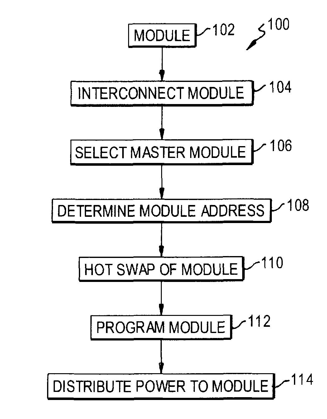
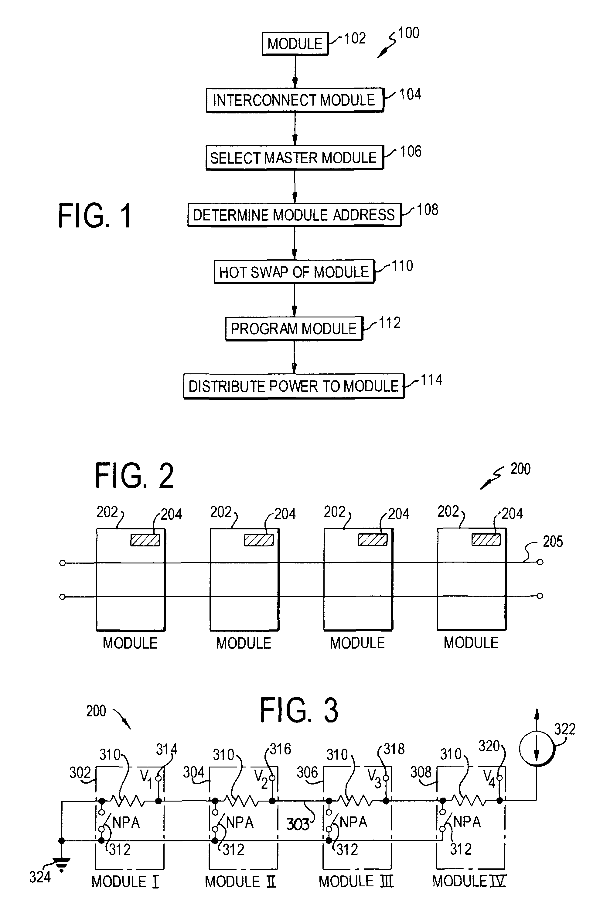
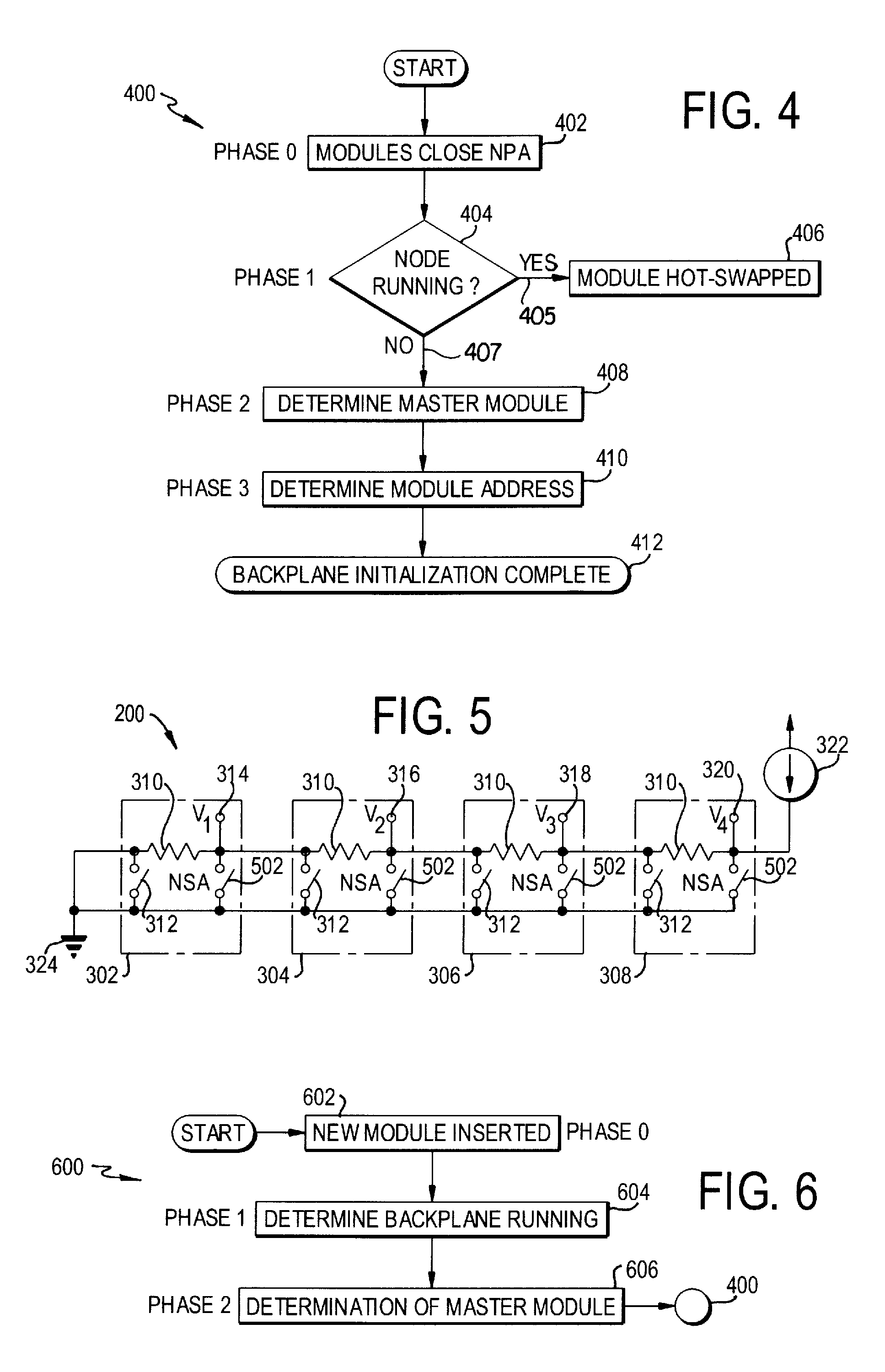
[0030]FIG. 1 illustrates a block diagram of a preferred embodiment of the node process 100. At least one module 302, 304, 306, or 308 (FIGS. 2, 3, and 5) is provided at step 102, and includes its associated set of hardware resources and a user-programmable microprocessor 204 (FIG. 2). The node 200 (FIGS. 2, 3, and 5) is constructed by interconnecting one or more of the microprocessor-based modules 302-308 at step 104 and forming a parallel-processing environment with a selected functionality. The modules 302-308 are housed in an assembly having watertight housings 202 (FIG. 2) that can be interconnected and permit the modules 302-308 to be interconnected at step 104 in accordance with the device and methods disclosed in U.S. patent application Ser. No. 11 / 085,232, now U.S. Pat. No. 7,476,802, entitled “Programmable Automation Controller Assembly”, which claims priority to U.S. Provisional Application Ser. No. 60 / 554,915, the contents of which are incorporated herein.

[0031]The module...


PUM


Abstract

An apparatus and method for forming a control node in a programmable architecture, is disclosed. The node includes a plurality of user-programmable, microprocessor-based modules connected together. The modules are connected to create a parallel-processing environment with a selected functionality. Hot-swapping of the modules can be determined in the node. Power is distributed throughout the modules in the node. The modules may be automatically programmed to accommodate a target independent device.

Description

RELATED APPLICATION[0001]The present application claims priority to U.S. Provisional Application Ser. No. 60 / 554,905, filed Mar. 22, 2004.FIELD OF THE INVENTION[0002]The present invention is generally related to control and, more particularly, to an apparatus and method for forming a control node using programmable modules.BACKGROUND OF THE INVENTION[0003]The terms control and control systems generally refer to the control of a device, process or system by monitoring one or more of its characteristics. This is used to insure that output, processing, quality and / or efficiency remain within desired parameters over the course of time. In many control systems, digital data processing or other automated apparatus monitor a device, process or system and automatically adjust its operational parameters. In other control systems, such apparatus monitor the device, process or system and display alarms or other indicia of its characteristics, leaving responsibility for adjustment to the operat...

Claims


Application Information

Patent Timeline
Patent Type & Authority Patents(United States)
IPC IPC(8): G05B19/18G06F15/16G05B19/042H04L12/26H04L12/28
CPCG05B19/0421G05B2219/25428H04L12/2602H04L43/00
Inventor CANE, GARY R.LEBAUDY, ANDRESSTOLZENBERG, JAYKELSEY, PATRICK J.
Owner FAIRMONT AUTOMATION
Learn More