
Heated catalyzed fuel injector for injection ignition engines

a fuel injector and catalytic technology, which is applied in the direction of machines/engines, combustion air/fuel air treatment, mechanical equipment, etc., can solve the problems of inability to maintain a liquid phase or re-compress to a liquid phase, inability to maintain a liquid phase, and up to the practical compression limit of internal combustion engines, so as to reduce the energy content of the resultant fuel, reduce the need for heat input, and promote carbon formation

Inactive Publication Date: 2010-06-29
ECOMOTORS
View PDF37 Cites 26 Cited by
  • Summary
  • Abstract
  • Description
  • Claims
  • Application Information

AI Technical Summary

Benefits of technology

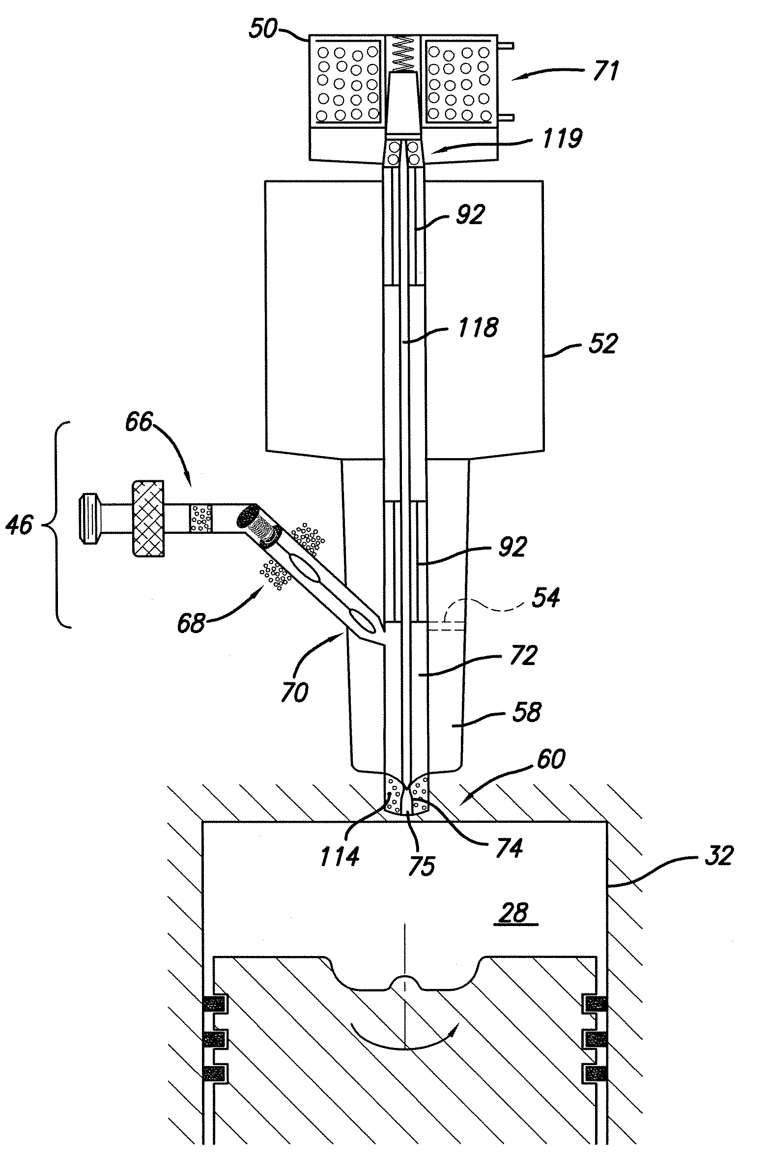
"The present invention relates to a system for injecting fuel into an internal combustion engine using heated catalyzed fuel injectors. These injectors can dispense fuel during the power stroke of the engine, providing better fuel vaporization and ignition. The fuel injector can operate at high pressure and can fire at room pressure or higher. The system uses oxygen reduction catalysts that are highly dispersed in the fuel, minimizing the formation of free radicals and reducing the degradation of the fuel. The injector-ignition system optimizes fuel vaporization and ignition timing, improving engine performance."

Problems solved by technology

In addition, the injector may fire at room pressure, and up to the practical compression limit of internal combustion engines.
There is, however, a point of pressure and temperature at which it is no longer possible to maintain a liquid phase or re-compress to a liquid phase.
Above the critical temperature and pressure, it is no longer possible to form a liquid, so the molecules interact in the gas phase even though they may be compressed beyond the density of a corresponding liquid.

Method used


Image

  • Heated catalyzed fuel injector for injection ignition engines
  • Heated catalyzed fuel injector for injection ignition engines
  • Heated catalyzed fuel injector for injection ignition engines

Examples


case ii

[0067]In Case II, the internal nickel molybdenum catalyst of the fuel injector was activated by operating the injector body at a temperature of approximately 750° F. In operation, the engine instantly fired and accelerated rapidly over a broad range of timing conditions. A preferred electronic timing was determined to be about 0.7 ms before top dead center, and the preferred timing was not sensitive to engine warm up. In addition, exhaust gas temperature was substantially lower than that found in Case I, indicating higher engine efficiency.

[0068]In Cases III and IV, the fuel mixture was changed to approximately 30% laboratory cetane, 60% heptane, and 10% ethanol by volume. In Case III (similar to Case I), the diesel engine including a fuel injector of the invention was tested under room temperature injector operation (i.e., not under heated conditions). At room temperature, the engine would not operate with this fuel mix.

[0069]In Case IV (similar to Case II), the internal nickel mol...


PUM


Abstract

The present invention provides an injector-ignition fuel injector for an internal combustion engine, comprising an input fuel metering system for dispensing a next fuel charge into a pressurizing chamber, a pressurization ram system including a pressurization ram for compressing the fuel charge within the pressurizing chamber, wherein the fuel charge is heated in the pressurization chamber in the presence of a catalyst, and an injector nozzle for injecting the heated catalyzed fuel charge into a combustion chamber of the internal combustion engine.

Description

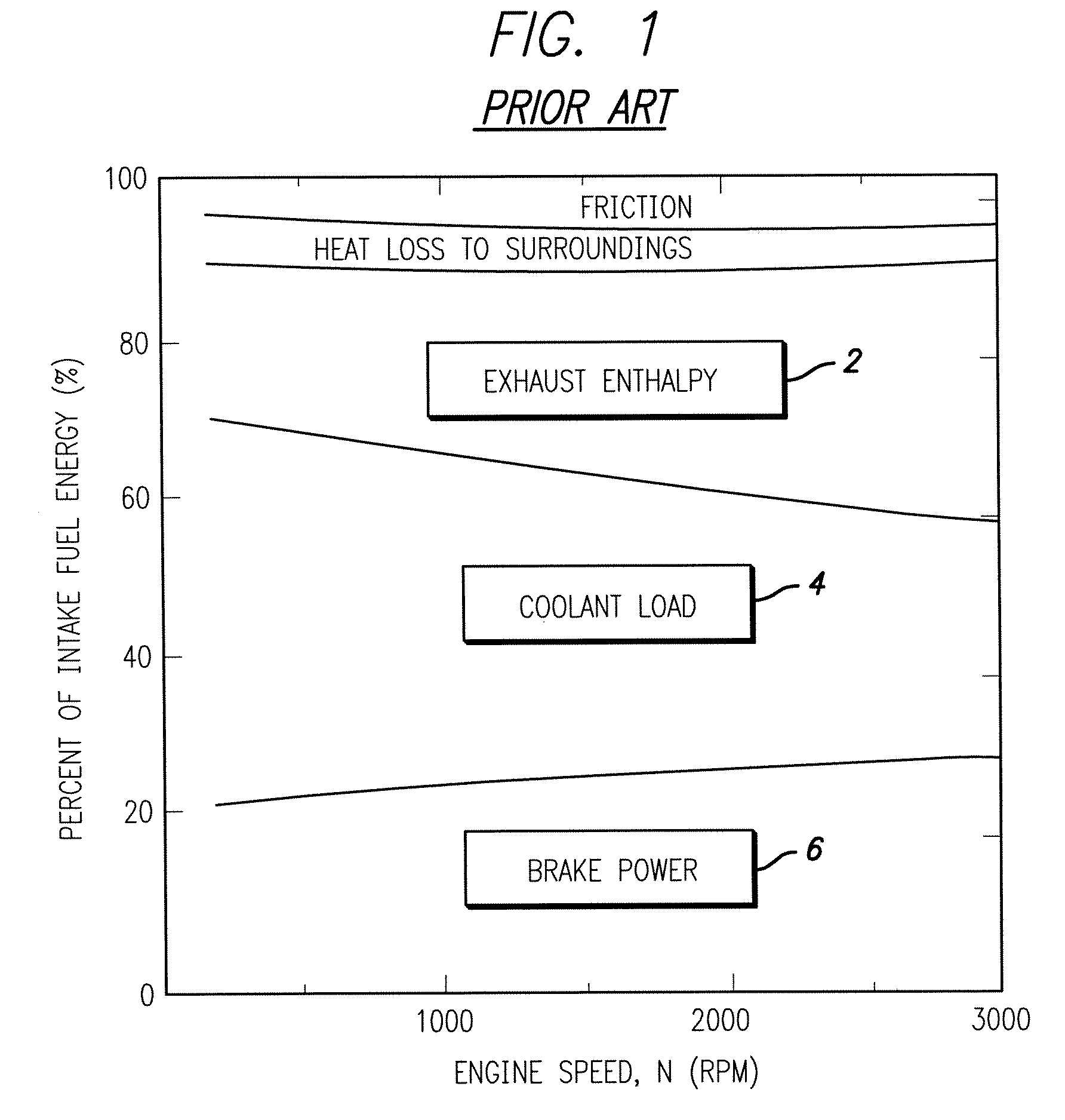
REFERENCE TO RELATED APPLICATIONS[0001]This application claims the benefit of U.S. Provisional Patent Application No. 60 / 787,964, filed Mar. 31, 2006, the content of which is incorporated herein by reference in its entirety.FIELD OF THE INVENTION[0002]The invention broadly relates to fuel injection systems and more particularly to a heated catalyzed fuel injector for injector-ignition engines.BACKGROUND OF THE INVENTION[0003]Much of the world's energy consumption is dedicated to powering internal combustion based vehicles. Most gasoline and diesel car engines are only 20-30% efficient, such that a major portion of the hydrocarbon fuels is wasted, thereby depleting global resources while producing an excessive quantity of pollutants and greenhouse gasses. As illustrated in FIG. 1 (prior art), about one third of the energy used by a conventional engine manifests itself as waste heat in the cooling system (coolant load 4) while another approximately one third of the energy goes out the...

Claims


Application Information

Patent Timeline
Patent Type & Authority Patents(United States)
IPC IPC(8): F02M51/00
CPCF02M51/04F02M53/02F02M53/06F02M69/18F02M57/027F02M69/045F02M69/047F02M57/00F02M25/10
Inventor CHEIKY, MICHAEL C.
Owner ECOMOTORS
Learn More