
Buried pipe examining method

a buried pipe and deteriorating technology, applied in the direction of material analysis using wave/particle radiation, instruments, force/torque/work measurement apparatus, etc., can solve the problems of deterioration which is visually perceived, the failure to find deterioration in the outer circumference or inside of the pipe, and the increase of accidents such as cave-ins, water leakages, etc., to achieve high accuracy and high accuracy

Inactive Publication Date: 2010-04-06
SEKISUI CHEM CO LTD +1
View PDF14 Cites 40 Cited by
  • Summary
  • Abstract
  • Description
  • Claims
  • Application Information

AI Technical Summary

Benefits of technology

The present invention provides a method for examining deteriorated pipes in a sewer pipeline or agricultural pipeline to determine the type and degree of deterioration without being affected by the environment in which the pipe is buried. The method involves measuring waves in the pipe using an impact elastic wave test and analyzing the frequency spectrum of the waves to determine the type of deterioration. The method can be used to examine a variety of types of pipes and can provide accurate results even when the pipe is buried underground. The method is simple and easy to use and can be performed quickly and with high accuracy.

Problems solved by technology

Number of accidents such as cave-ins, water leakages, and the like, of sewer pipelines and agricultural pipelines is increasing year by year due to corrosion and abrasion or breakage of aging buried pipes.
With such a method, however, only a deterioration which is visually perceived can be detected, a deterioration in the outer circumference or inside of a pipe fails to be found.
Therefore, it is difficult to quantitatively detect a deterioration phenomenon as appropriate.
It is also necessary to extract a large amount of core so as to collect quantitative data, so that the strength of a sewer pipeline or an agricultural pipeline is impaired, or much time and effort are required to conduct work.
However, since this examination system utilizes a reduction in the propagation energy of elastic waves or the counted number of elastic waves (the counted number of amplitudes exceeding a predetermined value), the system is easily affected by a situation surrounding a buried pipe, resulting in poor examination accuracy.Patent Document 1: JP H10-142200 APatent Document 2: JP H09-269215 A

Method used


Image

  • Buried pipe examining method
  • Buried pipe examining method
  • Buried pipe examining method

Examples


embodiment 1

[0076]In this embodiment, an impact elastic wave test is conducted as follows.

[0077][Input Method]

[0078]As an input device, an impact tool, such as a hammer, a steel ball, an impulse hammer or the like, can be used. Particularly, as an input device, to reflect input information during analysis, it is desirable to impact with a constant force using an impact tool capable of measuring input information as numerical values, e.g., a Schmidt hammer, a spring, a piston or the like. Also, for example, a method of swinging a hammer, a steel ball or the like with a constant force using a Schmidt hammer, a spring, a piston or the like, or a method of dropping a steel ball or the like from a constant height, is desirable.

[0079][Reception Method]

[0080]As a reception device, an acceleration sensor, an AE sensor, a vibration sensor, or the like can be used. As a method of setting the reception device, the device may be fixed using a tape, an adhesive or the like, or may be attached by a hand, a p...

example 1

[0087]A specific example of the present invention will be described.

[0088][Preparation of Samples]

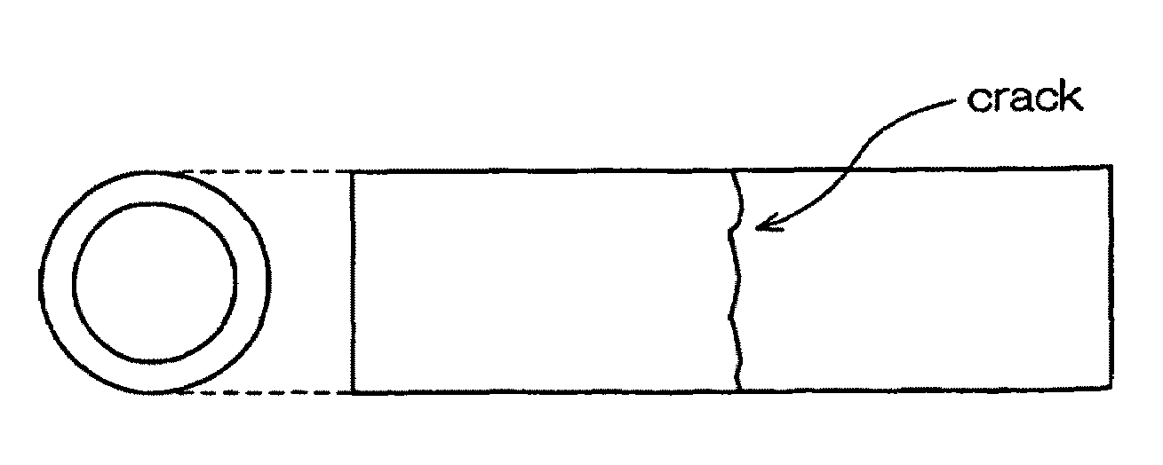
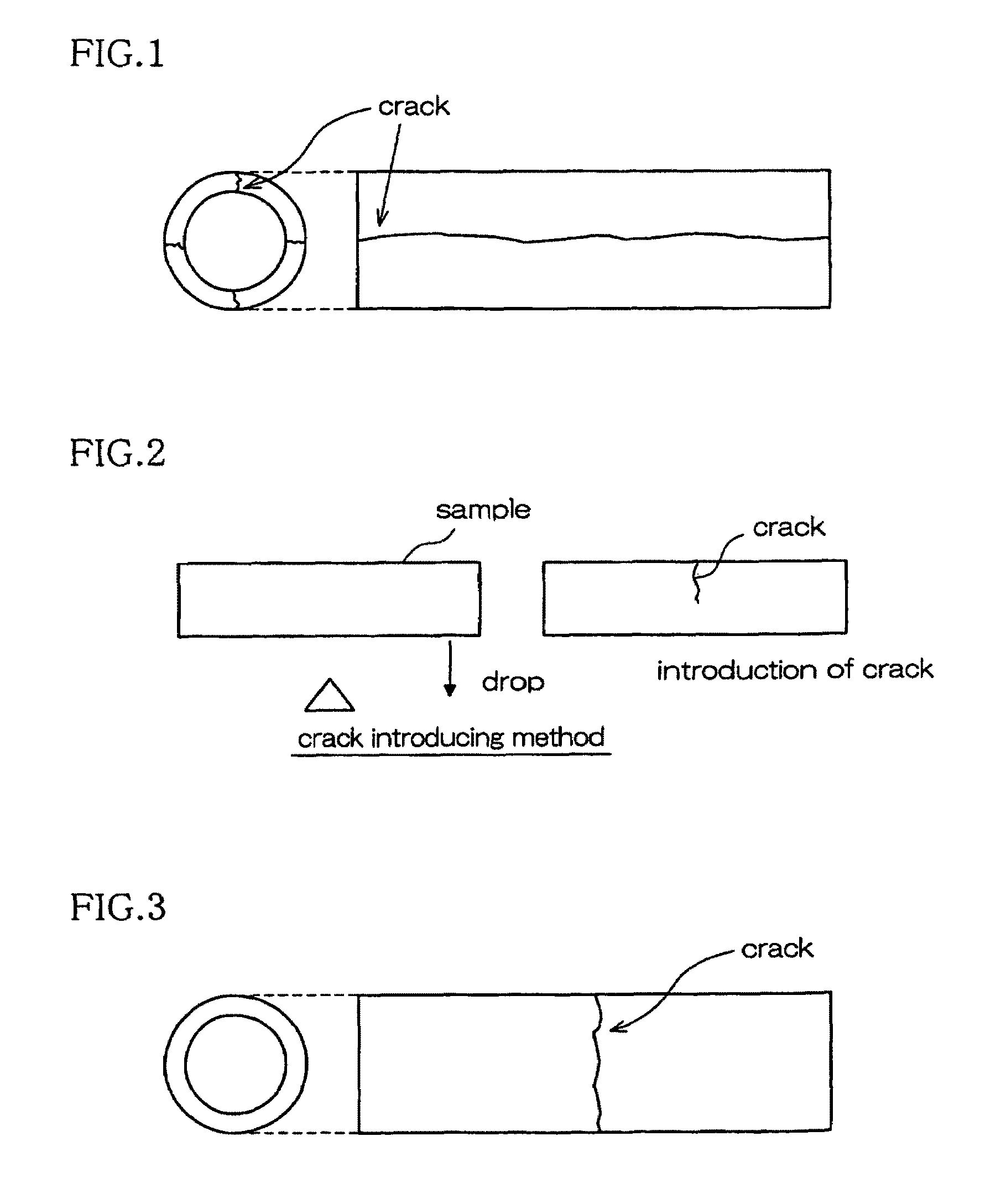
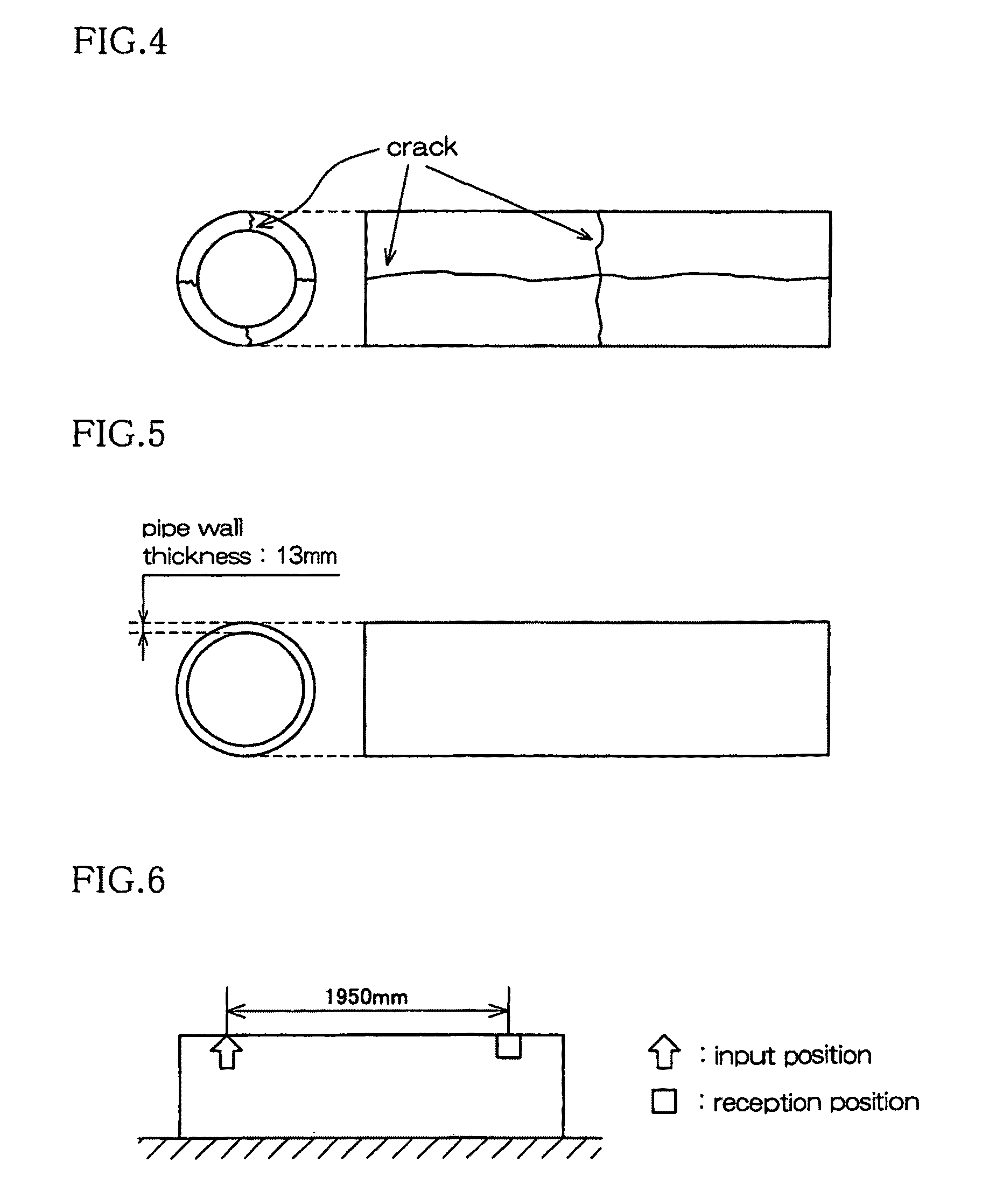
[0089]A concrete hume pipe (manufactured by Nippon Hume Corporation) having a nominal diameter of 250 mm (pipe length: 2 m) and conforming to the standards of JIS A 5372 (Shape B, Type 1) was used to prepare the following samples.[0090]Sample S1: Non-treated pipe (pipe wall thickness: average 28 mm). Note that the pipe wall thickness was measured in the vicinity of end surfaces of the pipe (10 points for each end; a total of 20 points) using a vernier caliper.[0091]Sample S2: Axial Crack-Introduced Pipe[0092]A load test machine capable of applying a line load to a sample was used to generate four cracks (crack width=0.15 mm) in an axial direction (see FIG. 1). Note that the number of cracks occurring in an end surface (inner and outer surfaces) was confirmed by visual inspection.[0093]Sample S3: Circumferential Crack-Introduced Pipe[0094]A crack having a crack width of 1.3 mm (see FIG. ...

embodiment 2

EXAMPLE 2

[0123]Firstly, a sample pipe and each test method used in this example will be described.

[0124]Sample Pipe

[0125]A concrete hume pipe (manufactured by Nippon Hume Corporation) having a nominal diameter of 250 mm (pipe length: 2 m) and conforming to the standards of JIS A 5372 (Shape B, Type 1) was used.

[0126]Loading Test with Line Load (External Pressure Test)

[0127]As shown in FIGS. 13(a) and (b), a line load 1 having a shape extending along an axial direction of a sample pipe P was placed on the sample pipe P from the top. Also, as shown in FIG. 14, a high-sensitivity displacement gauge 2 was placed inside the sample pipe P along a perpendicular direction, to measure a displacement of the sample pipe P when the line load 1 was applied to the sample pipe P, thereby obtaining a load-displacement curve.

[0128]Here, the placement of the line load 1 was not continuously conducted. The line load 1 was removed every a predetermined step (see FIG. 13(b)), i.e., the line load 1 was i...


PUM

PropertyMeasurementUnit
frequencyaaaaaaaaaa
frequencyaaaaaaaaaa
frequencyaaaaaaaaaa

Abstract

An impact elastic wave test is conducted to measure propagating waves in a pipe to be examined, a frequency spectrum of the propagating waves is analyzed, and at least a spectral area value in a first frequency region and a spectral area value in a second frequency region of the frequency spectrum are evaluated, thereby determining a type of a deteriorated state of the buried pipe. A correlation relationship between a parameter obtained from a force-deformation relationship indicating a relationship between a force externally input to a sample pipe and a deformation of the sample pipe due to the force, and impact elastic wave test data obtained by conducting an impact elastic wave test with respect to the sample pipe is previously obtained, an impact elastic wave test is conducted with respect to a pipe to be examined to collect impact elastic wave measurement data of the pipe to be examined, and the actually measured impact elastic wave measurement data is evaluated based on the correlation relationship, thereby quantitatively determining a degree of deterioration of the pipe to be examined.

Description

TECHNICAL FIELD[0001]The present invention relates to a method for examining a deteriorated state of a buried pipe.BACKGROUND TECHNOLOGY[0002]Number of accidents such as cave-ins, water leakages, and the like, of sewer pipelines and agricultural pipelines is increasing year by year due to corrosion and abrasion or breakage of aging buried pipes. Therefore, there is a demand for appropriate diagnosis of the degree of pipe deterioration, and repair / replacement based on the result of the diagnosis.[0003]In order to diagnose for sewer pipelines and agricultural pipelines, it is generally necessary to put elemental zones constituting an exploration range in order of deterioration level, and find quantitative deterioration p levels, so as to prioritize repair / reconstruction works and determine work methods.[0004]Therefore, conventionally, external appearance is generally checked by visual inspection or a CCTV camera, and if necessary, a core is extracted and a physical property is examine...

Claims


Application Information

Patent Timeline
Patent Type & Authority Patents(United States)
IPC IPC(8): G01N29/04G01N29/46
CPCG01N29/045G01N29/11G01N29/46G01N2291/2636G01N2291/02827G01N2291/2634G01N29/04G01N29/12
Inventor MINAGI, TAKUSHIIIDA, HIROSHIASANO, MASANORIKAMADA, TOSHIRO
Owner SEKISUI CHEM CO LTD
Learn More