Thruster with electro-thermal thrust augmentation
a technology of electro-thermal thruster and thruster, which is applied in the field of thruster augmentation of liquid propellant rocket thrusters, can solve the problems of limiting the useful operational life of an ev, ev cannot be controlled or maneuvered, and severe weight and volume limitations of an ev, so as to improve the specific impulse (isp) of the ev's thruster, simplify the thruster design, and improve the resistance to hydrazine products
- Summary
- Abstract
- Description
- Claims
- Application Information
AI Technical Summary
Benefits of technology
Problems solved by technology
Method used
Image
Examples
second embodiment
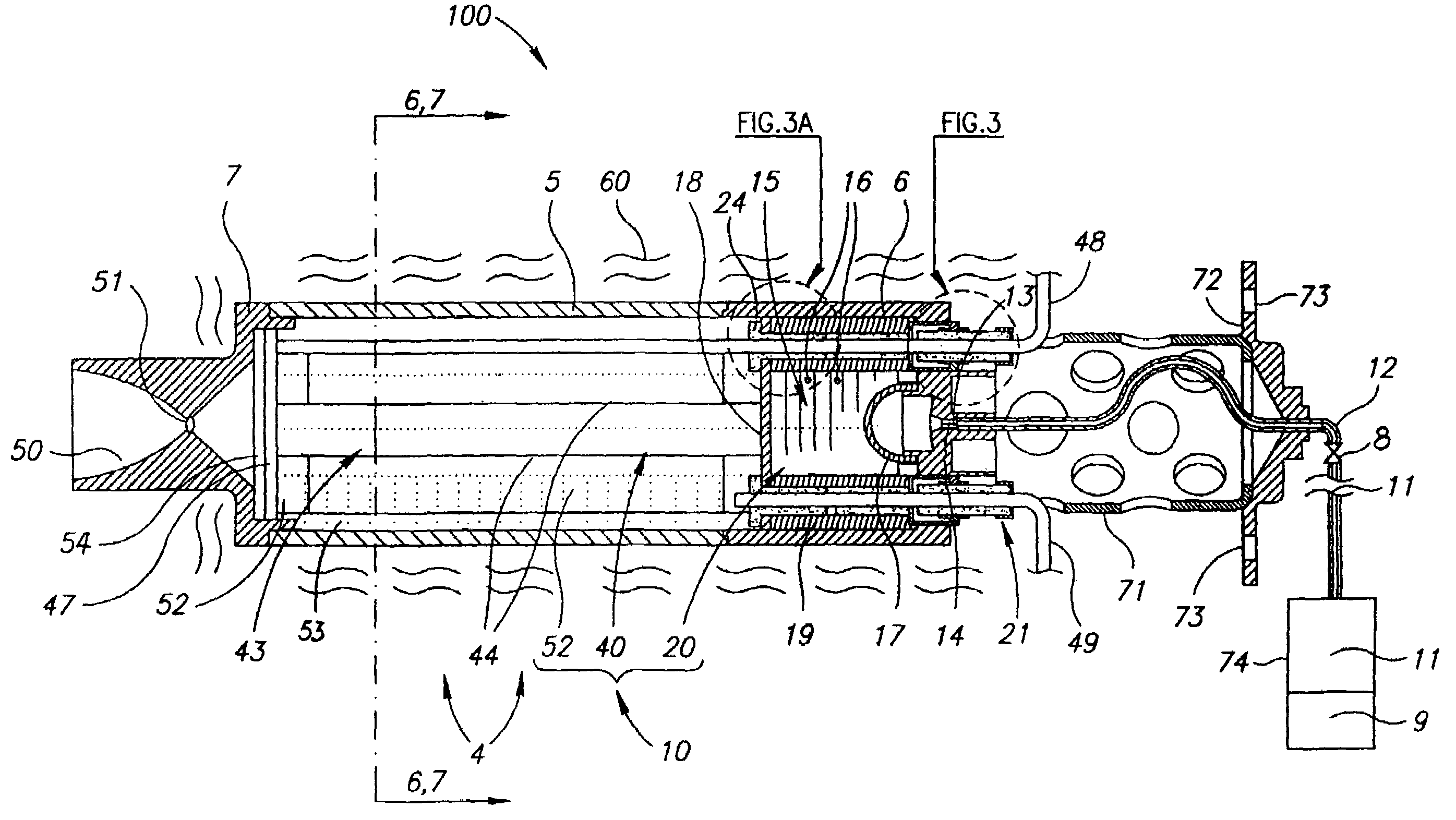
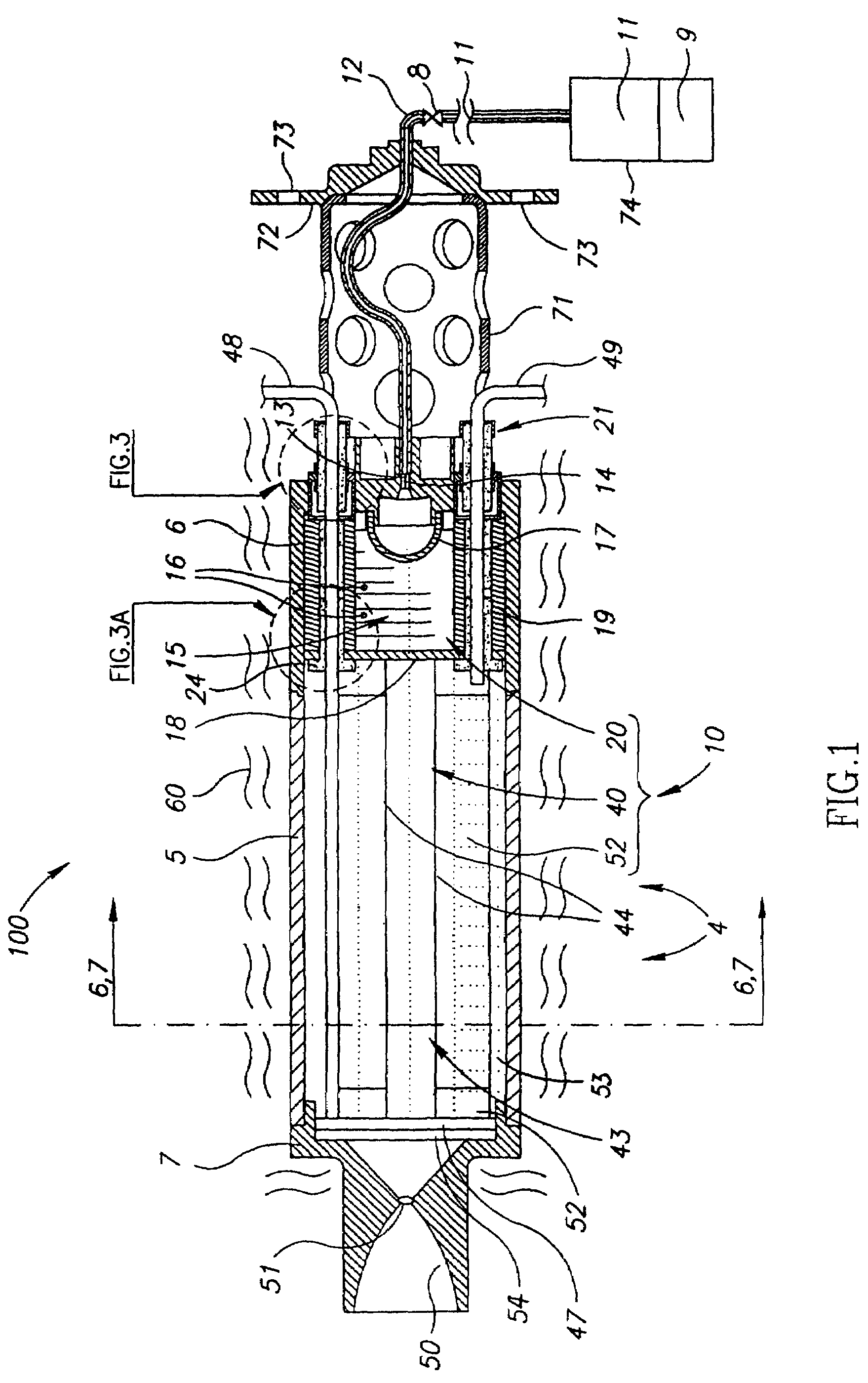
[0054]In the heating section 40, not shown in the figures, first and second U-shaped electric are provided and each have two longer straight longitudinal parallel arm portions and a shorter base portion. Each U-shaped resistor may be considered as implementing two resistors 44 coupled in series. Both U-shaped resistors may be disposed with their arm portions in parallel, and with their respective base perpendicularly adjacent to each other, downstream near the side of the discharge plug 7, which is indicated in FIG. 1. The arm portion of each U-shaped resistor may be covered by a coaxial concentric external tube 83, such as shown schematically by one short tube section in FIG. 2. Longitudinal fins may be accommodated inside each external tube 83 to firmly support a respective arm portion of each U-shaped resistor.
[0055]If desired, although not shown in the Figs., the first and second U-shaped resistors may be of identical shape and dimensions, but disposed with their base portion si...
fourth embodiment
[0065]In each one of the first, third, and fourth embodiment of the heating module 43, voids in the heating section 40 are filled with the catalyst 15, such as the pellets mixture 46, as indicated in FIGS. 6 and 7. The enhanced heat transfer properties of the additive serve to improve the heat exchange process resulting in higher gas temperature.
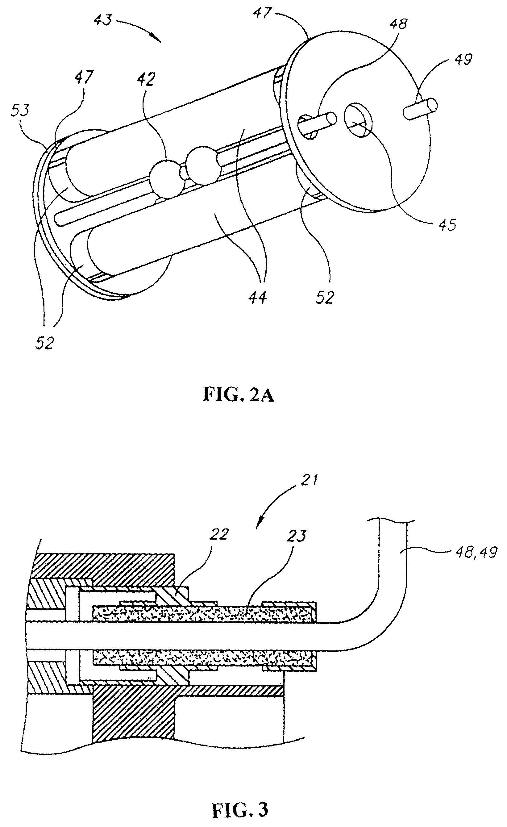
[0066]Ceramic rods 350, shown in FIG. 7, which duct the flow toward the center and along the axis of the heating section 40, are attached to sleeve 5 by means of a welded toggle, not shown in the Figs. In the first embodiments depicted in FIGS. 2A and 7, two electrically insulating holders 47, shown only in FIG. 2A, retain together resistors 44 and 244. Each insulating holder 47 has at least one aperture 45 accommodated to permit the flow of the hot gasses therethrough. In all of the shown configurations, screen 54 is attached to holder 47, at least adjacent discharge plug 7, to prevent spilling of the pellets mixture 46 through aperture 45....
PUM
| Property | Measurement | Unit |
|---|---|---|
| temperature | aaaaa | aaaaa |
| temperature | aaaaa | aaaaa |
| electrical power | aaaaa | aaaaa |
Abstract
Description
Claims
Application Information
 - R&D
- Intellectual Property
- Life Sciences
- Materials
- Tech Scout
- Unparalleled Data Quality
- Higher Quality Content
- 60% Fewer Hallucinations
Browse by: Latest US Patents, China's latest patents, Technical Efficacy Thesaurus, Application Domain, Technology Topic, Popular Technical Reports.
© 2025 PatSnap. All rights reserved.Legal|Privacy policy|Modern Slavery Act Transparency Statement|Sitemap|About US| Contact US: help@patsnap.com


